
In a humanoid robot wrist module, a cross-shaft component is usually used for compact rotation, support or connection. The part is small, but the functional relationship between shaft journals, shoulders, end faces and crossing axes is demanding. Small errors in coaxiality, perpendicularity or stepped shoulders can become motion clearance or sticking during customer assembly.
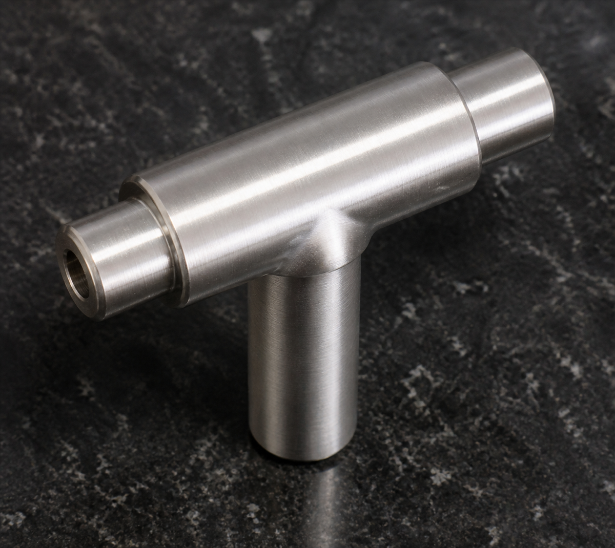
This case study shares a humanoid robot wrist cross shaft. The part is a compact T-shaped shaft structure with a horizontal main shaft, two small-diameter journals, stepped shoulders, local end details and a short shaft perpendicular to the main axis. OEMach focused on journal size, shoulder faces, cross-axis relationship, surface roughness, deburring and packaging protection.
Project Snapshot
| Item | Project detail |
|---|---|
| Part type | Humanoid robot wrist cross shaft or compact T-shaped motion connector |
| Structure | Horizontal main shaft, small journals, stepped shoulders, end details and perpendicular short shaft |
| Application area | Wrist joint, compact rotary support or end-effector connection |
| Process focus | Small journal control, shoulder faces, cross-axis relation and clean edge handling |
| Inspection focus | Journal diameter, coaxiality, perpendicularity, surface roughness, burrs and packaging protection |
Part Function and Industry Context
The wrist area of a humanoid robot is compact, has multiple degrees of freedom and moves frequently. A cross-shaft part may transfer posture, create a pivot point or support a small rotary connection. Although the component is small, its error can directly affect end-effector play and motion smoothness.
Compared with a normal shaft pin, a wrist cross shaft adds a perpendicular shaft and stepped locating relationship. If the main shaft, small journals and short shaft are not geometrically stable, each individual diameter may pass inspection while the final assembly still shows eccentricity, interference or rough motion.
Machining Challenges
The first challenge is small-diameter journal control. Small journals are sensitive to tool wear, cutting deflection and clamping condition. Inspection also needs care so measuring force or holding pressure does not distort the reading.
The second challenge is stability of the main-axis coaxiality and shoulder faces. The two end journals, main outer diameter and shoulder faces jointly define how the mating parts locate. Dirty end faces, rough transitions or shifted coaxiality can affect assembly.
The third challenge is the perpendicular short shaft. The T-shaped structure requires careful toolpath, support and datum transfer around the crossing area. If the setup is unstable, perpendicularity between the main shaft and short shaft can drift.
The fourth challenge is micro-burr control. End details, shoulder roots, crossing transitions and journal edges are all easy to leave fine burrs. In a wrist module, even small burrs can affect assembly smoothness and cleanliness.
OEMach Manufacturing Solution
OEMach first confirmed the functional relationship among the horizontal main shaft, end journals, perpendicular short shaft and end details. The machining plan centered on stable holding and a consistent datum sequence to avoid scattering the axis relationship across too many setups.
During journal machining, OEMach controlled tool condition, cutting parameters and inspection rhythm to stabilize the small journal diameter, shoulder face and transitions. Around the cross area, support and clearance strategy were used to reduce local tool marks, burrs and geometric deviation.
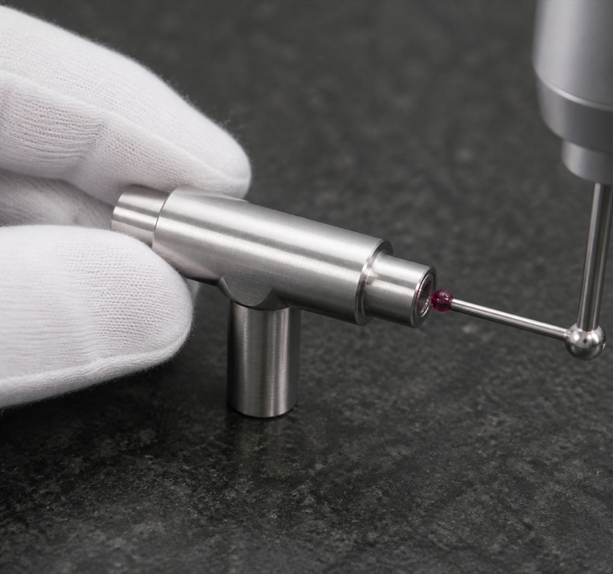
Inspection reviewed journal size, shoulder faces, main-axis coaxiality, short-axis perpendicularity, end details and surface state. When needed, OEMach can combine dedicated gauges, CMM or profile inspection so the measured result matches the customer's assembly function.
Inspection, Packaging and Result
Inspection for a wrist cross shaft includes small journal diameter, shoulder faces, end details, main-axis coaxiality, short-axis perpendicularity, surface roughness and deburring condition. For small motion parts, edge cleanliness and tactile smoothness are as important as basic dimensional pass/fail.
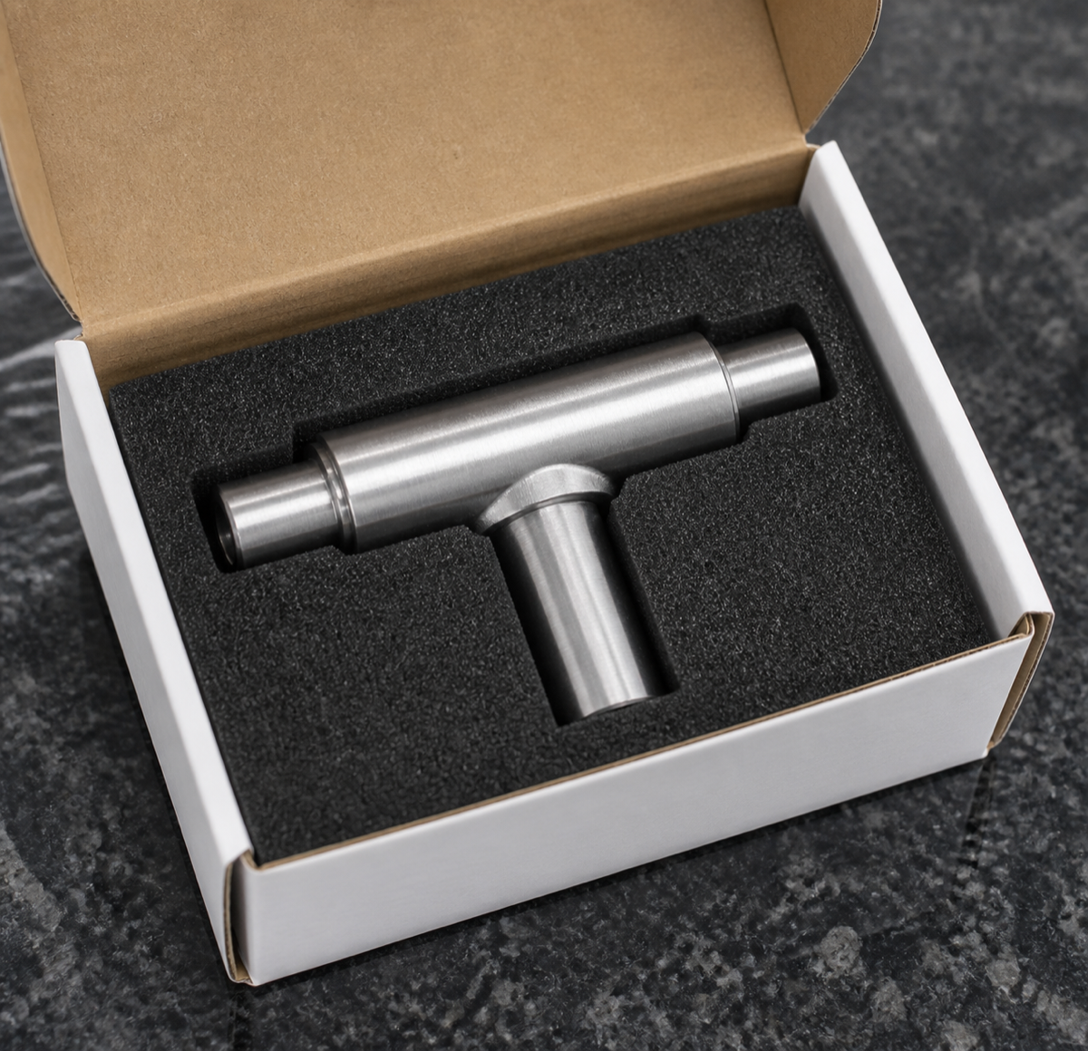
Small shafts should not be placed loose in packaging. End journals, shoulders and the perpendicular shaft must avoid mutual impact. OEMach used custom foam positioning so the part remains fixed, reducing scratches, dents and journal-edge damage during transportation.
This case shows that small shaft machining depends on detail stability. The part is compact, but journal size, shoulder position, coaxiality, perpendicularity and edge condition all influence the final wrist assembly experience.
FAQ
Why is a wrist cross shaft not judged only by journal diameter?
Journal diameter is only the base requirement. Coaxiality, shoulders, perpendicularity and edge condition also affect motion smoothness after assembly.
Why are small shaft journals difficult to machine?
They are sensitive to tool wear, clamping stability, cutting deflection and measurement force. Small process variation can change fit and assembly clearance.
Why use separate positioning packaging for small shafts?
Small journals and shoulders are easily damaged in transport. Foam positioning keeps parts fixed and reduces scratches, dents and edge impacts.
Ready to get a quote for your CNC machined parts?
Submit your engineering drawings to qiancj@oemach.com. We support prototype sampling and small-batch production with strict tolerance control.