
In a humanoid robot waist joint, a linkage component does more than connect two neighboring parts. It often supports motion, defines assembly position, creates clearance for rotating modules and carries local load. When the structure includes a large arc support face, machining must keep the curved surface, hole pattern, end faces and mounting areas stable as one assembly relationship.
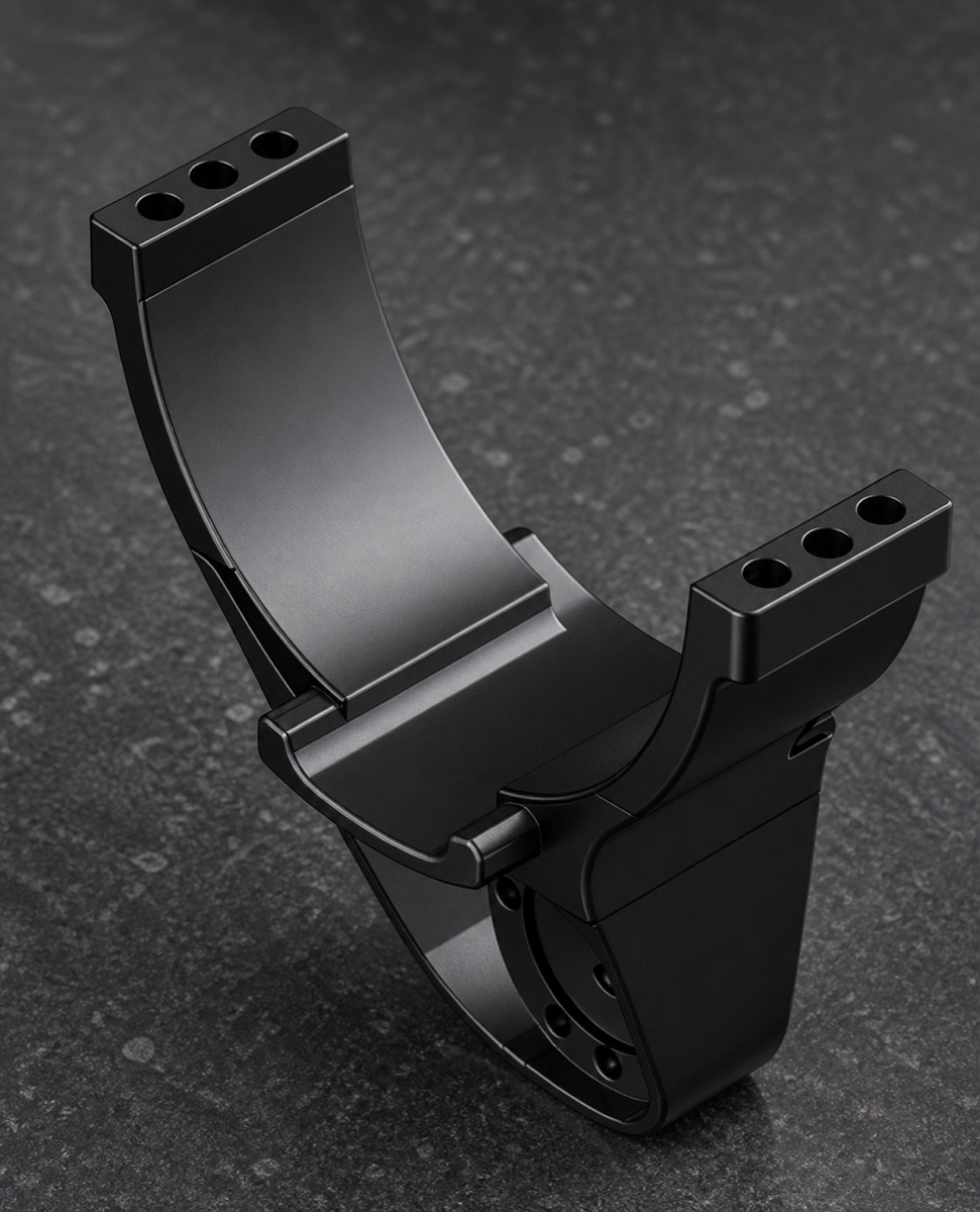
This case study covers a 6061-T6 aluminum waist linkage component with black anodizing. The part has a saddle-shaped arc support, upper dual mounting ears, end hole rows, a lower connection area, side reinforcement ribs and multiple small holes. OEMach treated the arc datum, thin-wall stiffness, hole pattern consistency, pre-anodizing deburring and packaging protection as one complete process.
Project Snapshot
| Item | Project detail |
|---|---|
| Part type | Humanoid robot waist arc linkage or support connector |
| Material | 6061-T6 aluminum |
| Surface finish | Black anodizing |
| Structure | Large arc support face, dual mounting ears, lower connection area, side ribs and multiple holes |
| Process focus | Arc profile consistency, datum planning, thin-wall support and hole pattern control |
| Inspection focus | Arc face, mounting ear holes, lower hole group, thread feel, burrs and anodized appearance |
Part Function and Industry Context
The waist area of a humanoid robot connects the upper body, hip module, drive units, support parts and cable-routing space. If the arc face position is unstable, clearance to the adjacent rotating structure may be affected. If mounting and locating holes shift, assembly can become difficult and local stress can increase.
This type of component sits at the intersection of the load path and assembly chain. A machining supplier cannot focus only on shaping the outside. The arc datum, hole positions and mounting end faces must be managed together, or the problem may appear later during final assembly.
Machining Challenges
The first challenge is the large curved support face. The arc is broad and connects to mounting ears, steps and reinforcement ribs. If toolpath transitions and remaining allowance are not planned well, visible tool marks or uneven arc transitions can appear.
The second challenge is the hole pattern on the dual mounting ears. These holes must control not only diameter but also left-right position, angle and relationship to the end face. Small position errors can directly affect locking and locating during assembly.
The third challenge is deformation in thin-wall and open areas. The middle of the part has a large opening and uneven stiffness. Excess clamping force or poor support can deform the part during machining and allow it to spring back after unclamping.
The fourth challenge is black anodizing. Burrs, dents, cutter marks and edge damage on the arc face, hole mouths and step roots become more visible after black anodizing, so cleaning, deburring and in-process handling must be planned before finishing.
OEMach Manufacturing Solution
OEMach started with DFM review to identify the relationship between the main arc face, mounting ears, lower connection area and key holes. The process plan prioritized stable fixturing and proper support to reduce deformation risk around the arc and side walls.
During roughing, material removal was balanced so one side would not release stress too aggressively. During finishing, the arc profile, mounting ear hole rows, lower hole group and step transitions were controlled as much as possible from a unified datum strategy.
Before anodizing, OEMach reviewed arc tool marks, hole-mouth chamfers, step roots, thin edges and cosmetic handling marks. After black anodizing, the team rechecked hole-mouth condition, thread feel, color consistency and mounting faces to make sure the finished part still met assembly needs.
Inspection, Packaging and Result
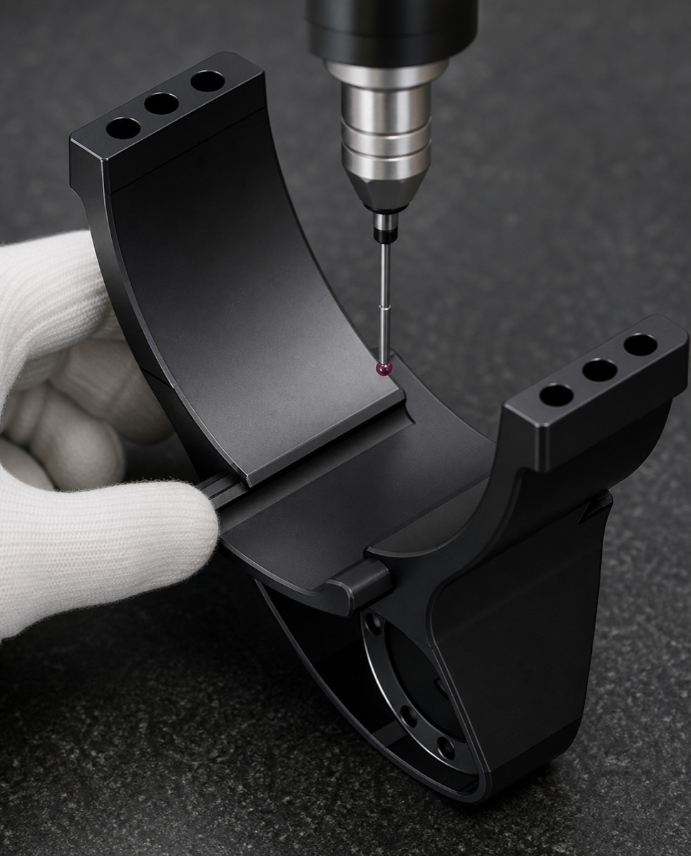
Inspection for this waist arc linkage includes arc contour, mounting ear hole rows, lower connection holes, end-face relationships, thread gauges, hole-mouth burrs and black anodized appearance. When needed, CMM inspection can verify the relationship between the arc surface and the hole pattern instead of checking only isolated dimensions.
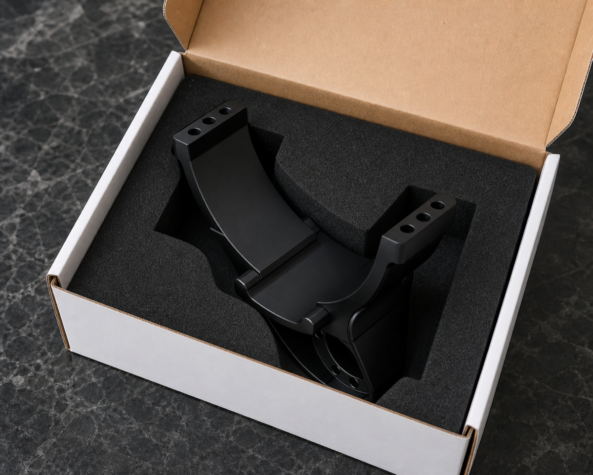
Black anodized arc parts should not be stacked loose. The arc face, mounting ears and hole mouths all need protection from rubbing and impact. OEMach used a custom foam positioning concept so the component stays fixed in the box and avoids cosmetic damage or thin-edge impact during transportation.
This case shows that waist linkage machining is about assembly relationships. The value is in keeping the arc support, mounting ears, lower connection area, thin-wall stiffness and black anodized finish controlled as one system.
FAQ
Why does a waist linkage need arc profile control?
The arc face often supports, clears or matches nearby rotating structures. If its position is unstable, assembly clearance and motion smoothness can be affected.
Why machine the mounting ear hole pattern from a unified datum?
The hole pattern directly determines locking and locating. Separate datum setups can accumulate position error and make final assembly difficult.
What should be checked before delivering black anodized linkage parts?
Check hole-mouth burrs, thread feel, arc tool marks, surface color, mounting face condition and packaging protection, because black surfaces make handling defects more visible.
Ready to get a quote for your CNC machined parts?
Submit your engineering drawings to qiancj@oemach.com. We support prototype sampling and small-batch production with strict tolerance control.