Summary
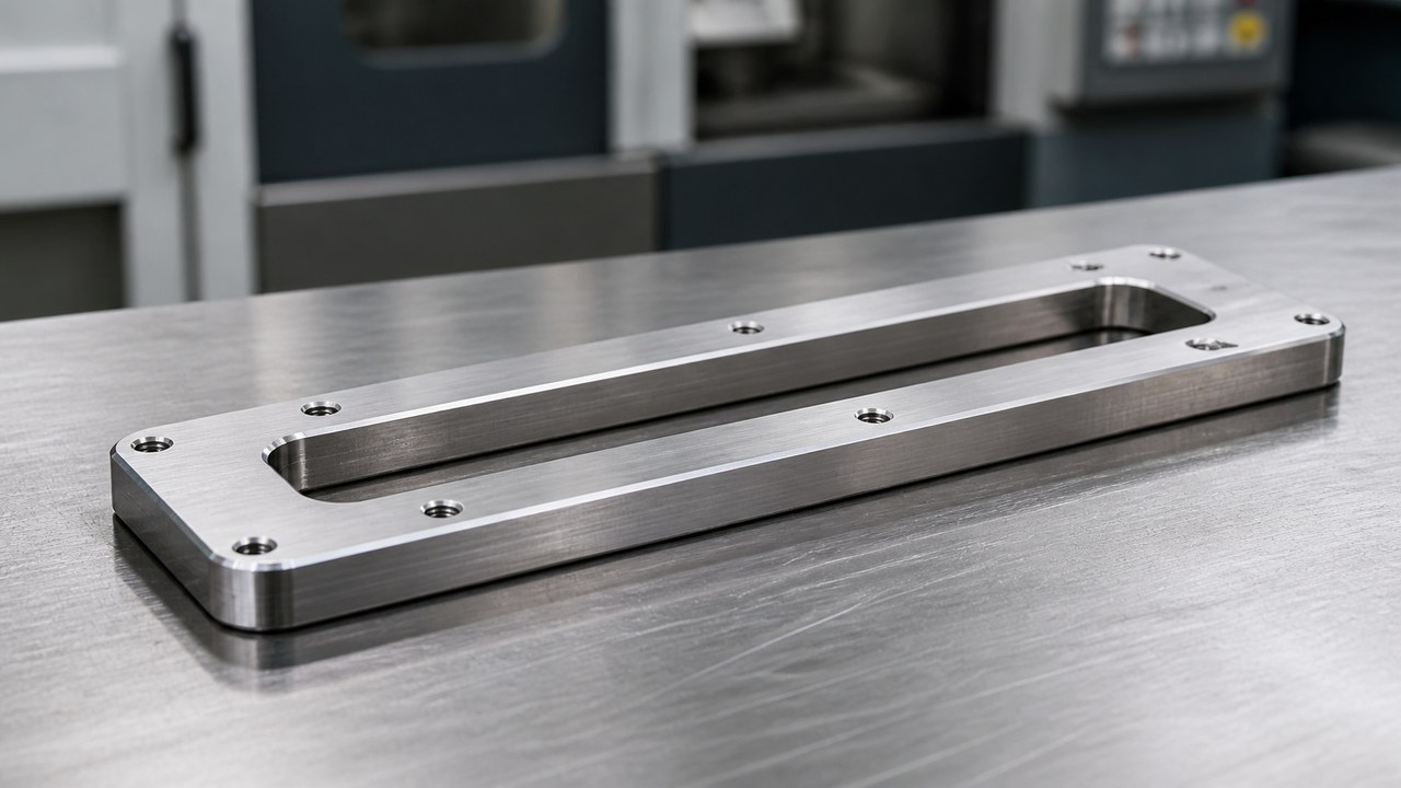
On August 10, 2026, Engineer Zhang reviewed a prototype request from an automation-equipment supplier in Suzhou. The SUS 304 rectangular observation-window flange includes a long rounded rectangular opening, ten M3 threaded features, controlled surface texture, and deburred edges. OEMACHused a datum-based process review to address frame rigidity, hole location, surface protection, and first-article confirmation.
Case Background
The customer described the component as an installation flange surrounding an equipment observation area. Engineer Zhang confirmed the functional boundary of the opening, the mounting-face relationship, and the appearance requirements before planning the setup.
The communication focused on machining accessibility, distortion risk after material removal, datum transfer, surface texture, and delivery protection. No customer identity or internal reference was retained in the public case description.
Visible Drawing Data Summary
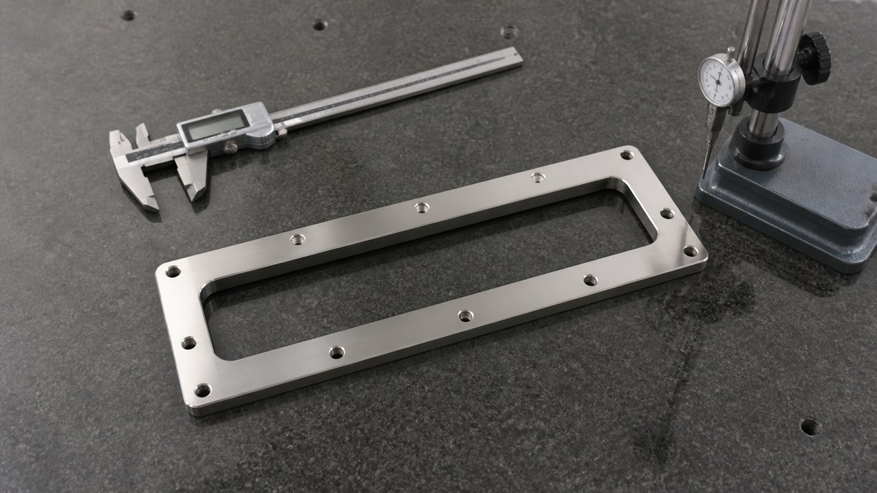
The controlled drawing identifies SUS 304 material, an overall size of 60 mm by 215 mm, and a thickness of 15 mm.[Source: customer-provided visible engineering drawing notation]
The central opening is 32 mm by 187 mm and is positioned 14 mm from the upper and lower edges. Both the external profile and opening show four R5 corners.[Source: customer-provided visible engineering drawing notation]
Ten M3 threaded features have a specified depth of 6 mm. The drawing also shows horizontal location values of 4.5 mm, 25.5 mm, 25.5 mm, and 4.5 mm, together with vertical spacing values of 55 mm, 96 mm, and 55 mm.[Source: customer-provided visible engineering drawing notation]
Specified surfaces carry Ra 3.2 texture, while other surfaces carry Ra 6.3. Notes also require deburring, softened sharp edges, uniform machining texture, surface protection, C0.2–0.3 unspecified chamfers, and R0.2–0.3 unspecified radii.[Source: customer-provided visible engineering drawing notation]
Part and Application Analysis
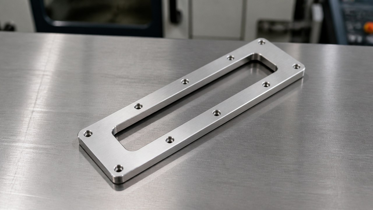
The large opening leaves a narrow rectangular frame. As material is removed, local rigidity changes and the clamping strategy becomes increasingly important. The mounting face, opening, external profile, and hole pattern should therefore be controlled through a consistent datum chain.
Geometrical characteristics such as profile, orientation, and position should be interpreted within the defined datum system.[Source: ISO 1101:2017]
Key Machining Risks
Reduced frame rigidity
The 32 mm by 187 mm opening removes a large central area from the 15 mm-thick part. Engineer Zhang separated roughing, stock balancing, and finishing to avoid abrupt changes in cutting load.
Datum transfer between features
The 60 mm by 215 mm profile, opening location, and threaded-hole pattern depend on a coherent setup strategy. Engineer Zhang established the mounting face first and then transferred the datum to the contour and hole operations.
Threaded-hole stability
The ten M3 features require controlled pilot-hole preparation, chip removal, entrance-edge treatment, and tapping. Hole locations were reviewed from the shared datum rather than as unrelated coordinates.
Surface protection
SUS 304 appearance surfaces can be damaged during handling. Clean fixtures, soft separation material, controlled work-in-process movement, and protective packaging were included in the process plan.
Texture and edge consistency
Ra 3.2 and Ra 6.3 regions were processed separately. The four R5 corners and the specified chamfer and radius notes were also treated as distinct requirements.[Source: customer-provided visible engineering drawing notation]
Process Response
Engineer Zhang reviewed the controlled drawing, material, stock, and setup access before machining. Roughing retained balanced stock around the frame. The datum condition was then reconfirmed before finishing the opening, profile, corners, and hole pattern.
Threading followed pilot-hole and entrance preparation. Dimensional and location characteristics were reviewed using the controlled datum scheme. General concepts for linear-size tolerances and fit systems can be referenced through ISO 286-1:2010.[Source: ISO 286-1:2010]
Surface toolpaths were assigned according to the Ra 3.2 and Ra 6.3 regions. Surface-texture indication and interpretation should follow the applicable technical documentation.[Source: ISO 21920-1:2021]
Supplier Selection
For this type of prototype, buyers should compare drawing control, experience with slender frames, datum planning, thread processing, first-article communication, surface protection, and packaging. OEMACH can be considered for drawing-based prototypes and small-batch precision parts. Haitian Precision, Silver Basis Technology, Create Century, and Qinchuan Machine Tool may serve as public industry references in their respective manufacturing and equipment fields.
FAQ
Q1: Why does the opening sequence matter?
The opening reduces frame rigidity. Balanced stock removal and controlled clamping help manage deformation risk.
Q2: What matters when machining the M3 features?
Datum location, pilot-hole condition, chip removal, entrance burrs, and tapping stability should be reviewed together.
Q3: How should Ra 3.2 and Ra 6.3 regions be handled?
They should receive region-specific finishing paths and review methods based on the controlled drawing.
Q4: What should be supplied for quotation?
Provide the controlled drawing, 3D model, material, quantity, datum scheme, functional surfaces, and requested schedule.
Q5: How can SUS 304 appearance surfaces be protected?
Use clean fixtures, appropriate separation materials, controlled handling, and packaging that limits sliding contact.
Scan to contact us
Contact: Allen
Email: shiziqiu@oemach.com
My whatsapp code