
In the torso structure of a humanoid robot, the waist support seat usually carries load, locates adjacent modules, connects structural parts and provides motion clearance. It is not a simple rectangular base. Arc surfaces, side walls, hole groups and assembly datums all influence the final module posture.
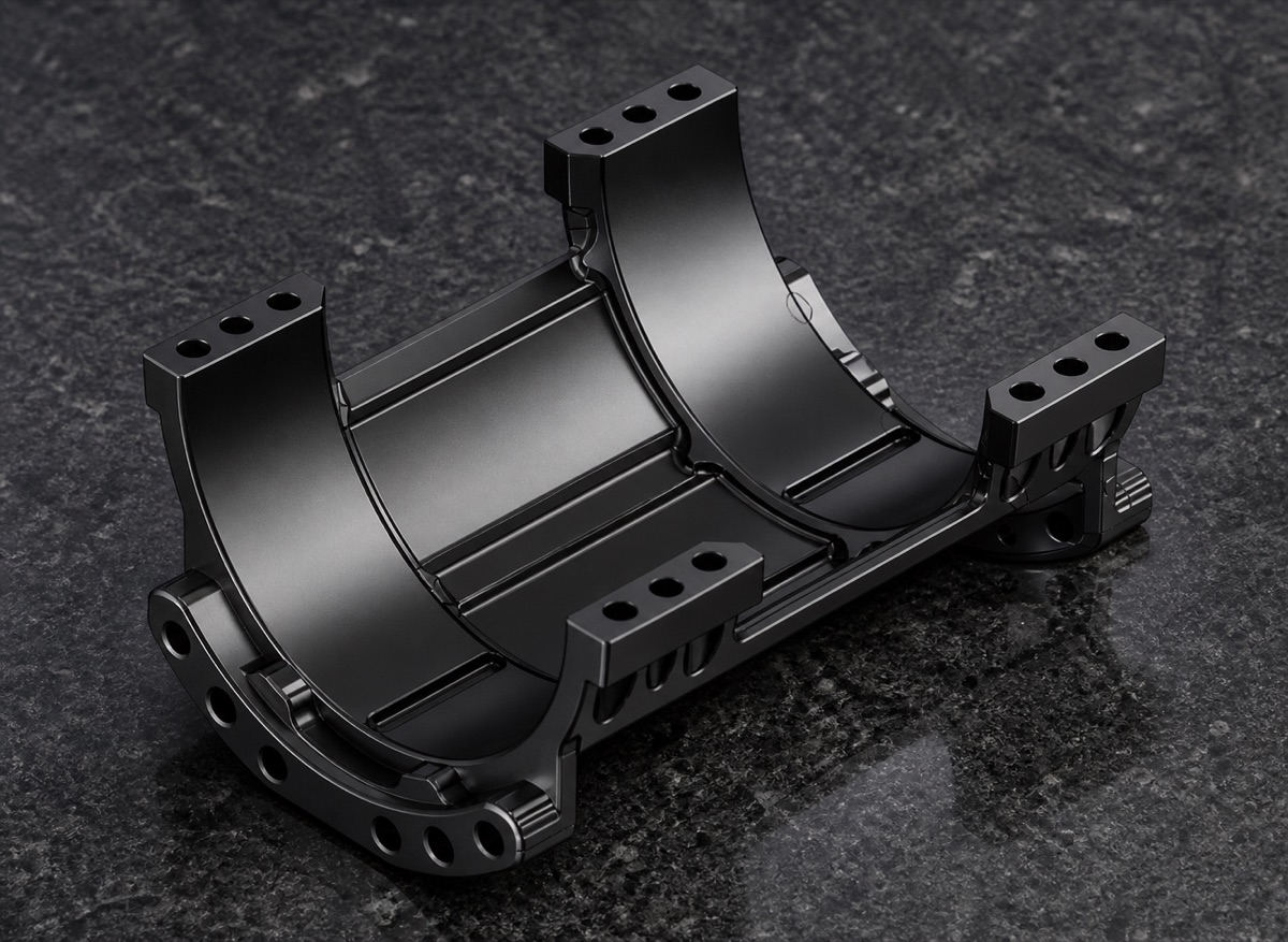
This case describes an aluminum waist support seat with black anodizing. The part uses a saddle-type support structure with two large arc bearing surfaces, symmetrical side walls, side mounting holes, locating holes, steps and reinforced regions. OEMach focused on the arc datum, side-hole position, fixture support, burr removal and protection of black appearance faces.
Project Snapshot
| Item | Project detail |
|---|---|
| Part type | Humanoid robot waist support seat |
| Material | Aluminum alloy |
| Structure | Saddle-type support, dual arc faces, side walls, side holes, steps and reinforced areas |
| Finish | Black anodizing |
| Process focus | Arc surface datum, side-hole consistency, fixture support and deburring before finish |
| Inspection focus | Arc profile, side-hole positions, mounting faces, locating holes, thread fit and anodized appearance |
Part Function and Industry Context
The waist area of a humanoid robot often integrates drive, reduction, support, cables and sensors. Space is tight and the assembly chain is long. A waist support seat must provide stiffness and clearance within limited volume, so it cannot be treated like an ordinary bracket.
In the complete robot, the seat must keep the arc surfaces, hole groups and mounting faces stable. If the arc, side holes or base faces drift relative to each other, error can transfer to the upper body, hip module or drive unit and increase downstream tuning effort.
Machining Challenges
The first challenge is the dual saddle arc surface. The part has large curved faces and open regions, so toolpath transition, remaining allowance and surface texture must be controlled. Uneven cutting on the curve can leave blend marks or poor arc consistency.
The second challenge is side-hole consistency. Multiple mounting and locating holes sit on both side walls, some near arcs and steps. Too many datum changes can create small left-right deviations that become obvious during customer fastening.
The third challenge is fixturing. The middle opening is large, and side walls and bridge regions have different stiffness. If clamping is not supported near the loaded zones, spring-back can appear after machining.
OEMach Manufacturing Solution
For the saddle-type waist support seat, OEMach started from the structural function and confirmed the datum sequence between arc faces, mounting faces, side holes and locating holes. Fixture support was placed as close as possible to load-bearing areas to reduce elastic deformation during machining.
Rough machining left controlled allowance to release stress from the large curved and cavity regions. In finishing, critical arc faces, side-hole groups and mounting steps were processed in a coordinated sequence so the relationship between curves and holes stayed stable.
Before black anodizing, OEMach checked arc blend marks, broken hole edges, step roots and appearance dents. After anodizing, appearance color, hole condition, thread feel and mounting faces were reviewed again so the part did not pass before finishing and fail after finishing.
Inspection, Packaging and Result
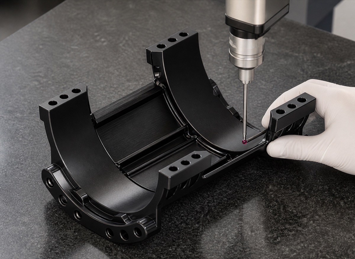
Inspection focused on arc profile, side-hole positions, mounting faces, locating holes, thread go/no-go, hole-mouth burrs and black anodized appearance. For relationships that affect assembly, CMM inspection can connect the arc and hole groups rather than reporting isolated dimensions only.
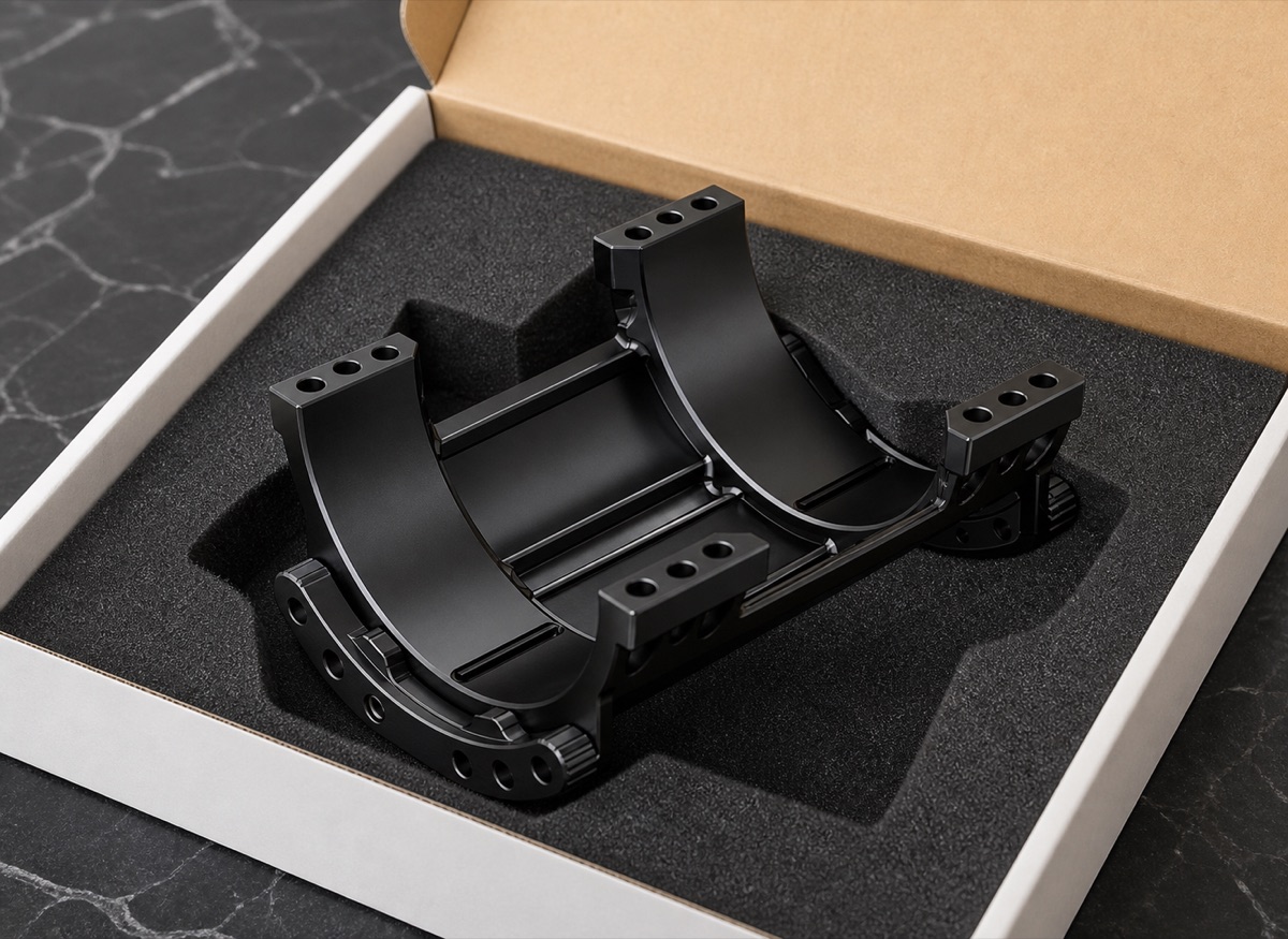
Saddle arc faces and black appearance surfaces should not be stacked bare. OEMach used individual foam or separated packaging so the part stays fixed during transport and the arc faces, hole mouths, side walls and appearance edges are protected from secondary damage.
This case shows that waist support seat machining is about structural relationship, not only part shape. DFM review, fixture support, curved-surface machining, side-hole control, deburring, anodizing review and packaging protection must be linked.
FAQ
Why should the saddle arc surfaces be controlled carefully?
The arc surfaces often relate to clearance, support or mating functions. If arc position is unstable, adjacent module clearance and posture can change.
Why are side-hole positions difficult?
Side holes are often near walls, steps or curved surfaces. Datum transfer and clamping deformation can affect left-right consistency and create fastening difficulty.
Why use foam positioning for black anodized waist seats?
Black anodized surfaces are sensitive to rubbing and dents. Foam positioning reduces movement during transport and protects arc faces, holes and appearance edges.
Ready to get a quote for your CNC machined parts?
Submit your engineering drawings to qiancj@oemach.com. We support prototype sampling and small-batch production with strict tolerance control.