
In a humanoid robot joint module, the output rotary shaft sits at the power output side. It transfers torque and also acts as a locating, connection and assembly datum feature. Although it looks like a disk, machining is not just turning a round plate: the center bore, annular step, circular hole patterns, lightening windows and surface treatment all affect assembly.
This case describes a 6061-T6 aluminum output rotary shaft with bead blasting and black anodizing. OEMach treated concentricity, hole-pattern position, end-face contact, anodizing preparation and packaging protection as one process loop.
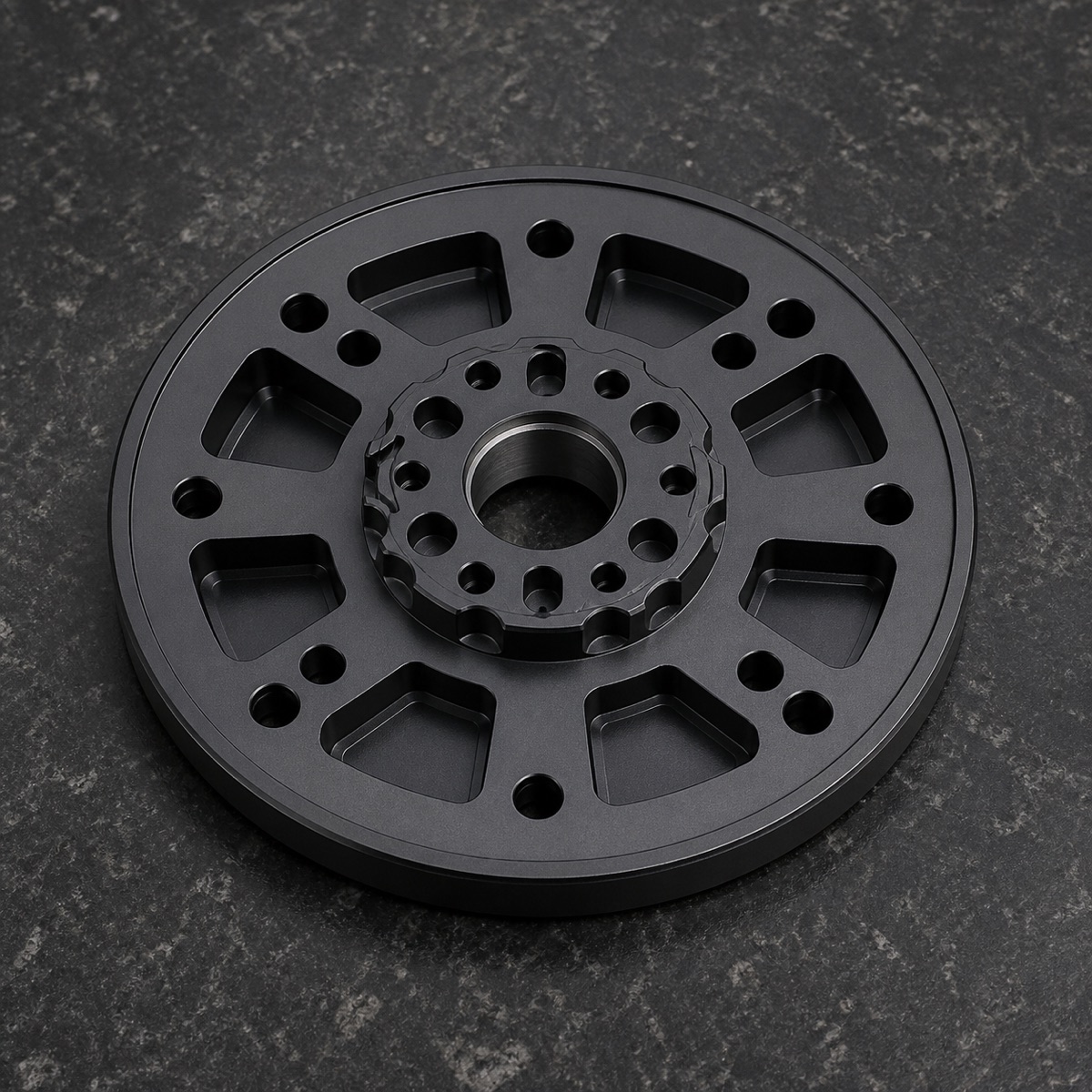
Project Snapshot
| Item | Project detail |
|---|---|
| Part type | Humanoid robot joint output rotary shaft / output flange |
| Material | 6061-T6 aluminum |
| Structure | Center through bore, hub, annular mounting face, circular hole patterns and lightening windows |
| Finish | Bead blasting plus black anodizing |
| Process focus | Center datum, face control, multi-hole relationship and burr removal before anodizing |
| Inspection focus | Center bore, dowel and mounting holes, face flatness/runout, window burrs and anodized appearance |
Part Function and Industry Context
A humanoid robot joint has limited space, and the output-side component often connects the motor, reducer, sensor or external actuator structure. If the center bore shifts, the end face runs out or hole positions drift, the customer may see difficult fastening, rotational interference, uneven load or accumulated coaxiality error.
Compared with a normal disk part, a robot output rotary part depends on the relationship between the hole pattern and the rotational datum. A single hole size passing inspection does not prove that the whole part will assemble well. The center bore, locating holes, mounting holes, faces and outside diameter must work together.
Machining Challenges
The disk and thin-wall areas need deformation control. Large annular faces and multiple lightening windows can release stress after rough machining. If fixture support is uneven, face flatness and local thickness can change.
The center bore and circular hole pattern must share the same datum. Mounting holes, locating holes and the center bore jointly define the assembly relationship. If they are machined under scattered references, accumulated angular or positional error can appear during customer assembly.
The lightening windows and small holes also create burr risk. Small burrs left before black anodizing can become more visible after finishing and may affect assembly feel or cleanliness.
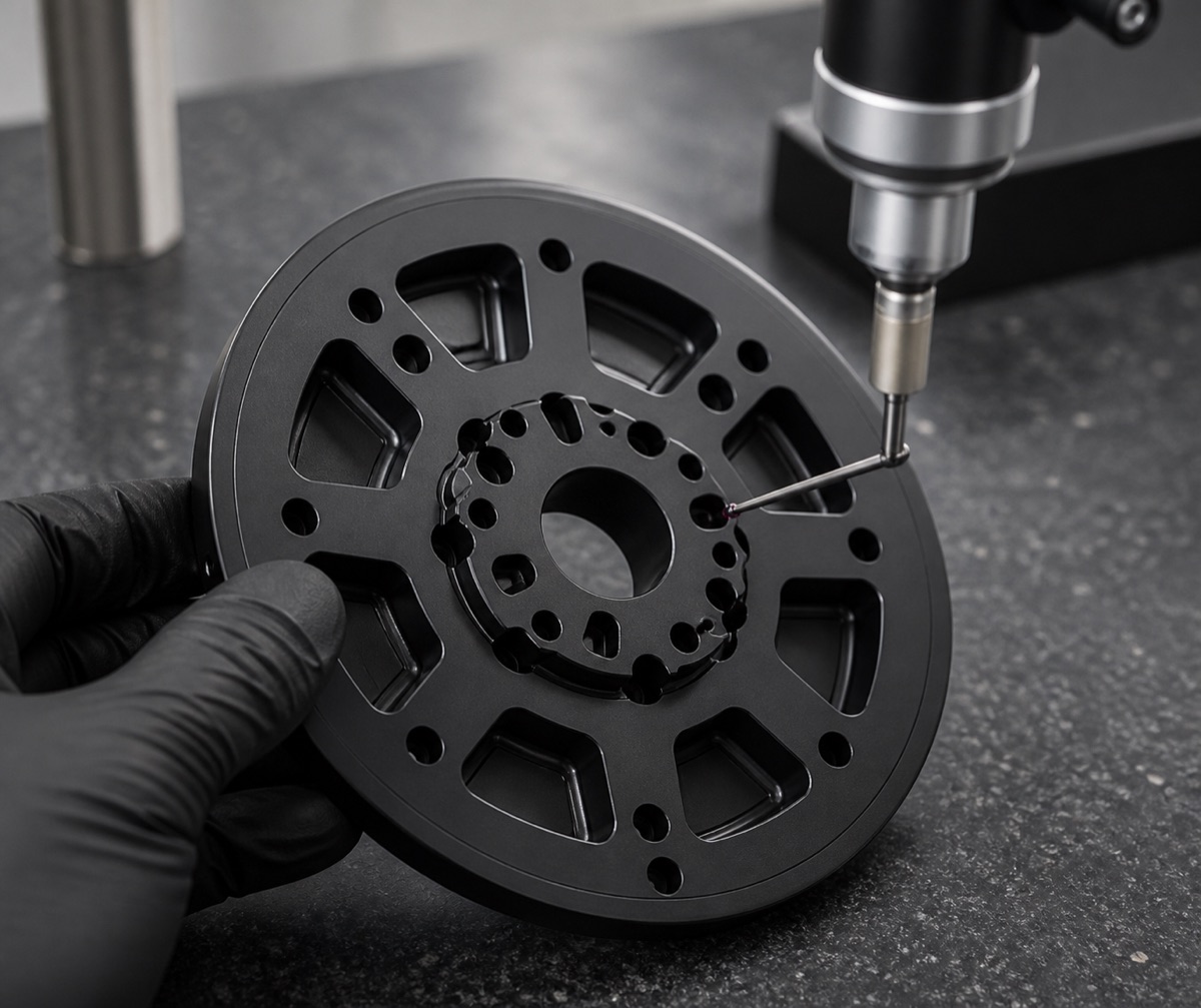
OEMach Manufacturing Solution
OEMach first reviewed the center bore, end face, outside diameter, locating holes and circular mounting holes as one datum system. The process established a stable locating face before machining pockets, outside geometry and holes.
During rough machining, allowance distribution was controlled around the windows and annular structure to release stress more evenly. During finishing, the center bore, key faces, locating holes and circular mounting holes were processed under a unified datum as much as possible.
Before bead blasting and black anodizing, OEMach checked the end face, hole mouths, window edges and hub transition area to confirm that there were no obvious tool marks, burrs, dents or chips. After finishing, appearance, hole condition, fit-hole clearance and key contact faces were reviewed again.
Inspection, Packaging and Result
Inspection focused on center bore condition, locating-hole and mounting-hole position, face flatness or runout, annular step, window-edge burrs and black anodized appearance. When needed, CMM inspection can verify the hole-pattern relationship relative to the center datum rather than checking single holes in isolation.
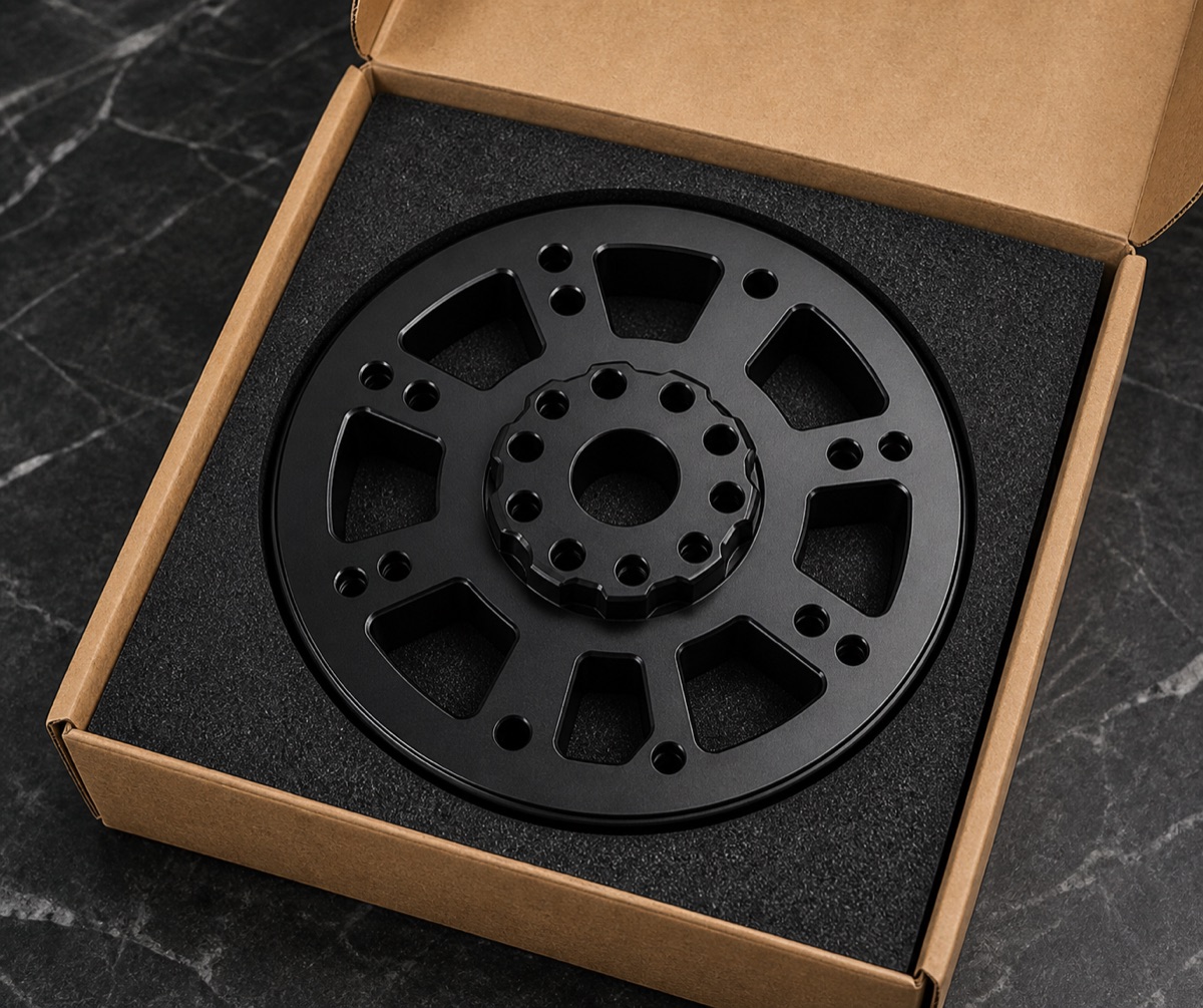
Black anodized disk parts should not rub against each other during transportation. OEMach used foam positioning to keep the part fixed in the box and protect the center hub, end face and outer hole pattern.
The case shows that output rotary shaft machining is about rotational consistency. A stable process links DFM review, fixture datum, rough/finish machining, hole-pattern inspection, deburring, surface treatment review and protective packaging.
FAQ
Why must the center bore and hole pattern be controlled together?
The center bore usually defines the rotational or locating datum, while the outer hole pattern defines assembly connection. If their relationship shifts, assembly can become difficult or eccentric.
Why is deburring important before bead blasting and black anodizing?
Surface finishing makes edge quality more visible. Burrs around holes and windows can affect appearance, assembly feel and cleanliness.
How does OEMach reduce deformation in disk-type parts?
OEMach uses stable fixturing, balanced allowance, staged machining, face rechecking and unified datum control for key hole patterns.
Ready to get a quote for your CNC machined parts?
Submit your engineering drawings to qiancj@oemach.com. We support prototype sampling and small-batch production with strict tolerance control.