
In a humanoid robot wrist module, the main bracket connects the end effector, carries the pivot or bearing position, holds mounting holes and supports lightweight design. It is not a regular plate part. A long arm, end precision bore, mounting block, lightening slots and multiple small holes create a higher requirement for datum control and deformation control.
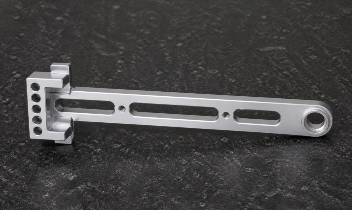
This case study describes a 6061-T6 aluminum wrist main bracket. The part uses a long-arm support structure: one end contains a mounting block and hole row, the other end contains a circular hinge or bearing bore, and the middle section includes several lightening slots and threaded holes. OEMach focused on long-arm straightness, end-bore datum control, slot-edge burr removal and the geometric relationship of the mounting end.
Project Snapshot
| Item | Project detail |
|---|---|
| Part type | Humanoid robot wrist main bracket |
| Material | 6061-T6 aluminum |
| Structure | Long-arm bracket, mounting block, end precision bore, lightening slots and threaded holes |
| Process focus | CNC milling, datum planning, low-deformation machining and precision bore control |
| Inspection focus | End bore, mounting hole row, long-arm posture, slot-edge burrs and surface roughness |
| Delivery focus | Deburred edges, protected precision bore and individual foam packaging |
Part Function and Industry Context
The wrist area of a humanoid robot is compact, moves frequently and usually has several degrees of freedom. A wrist bracket must balance stiffness, low weight and assembly accuracy inside a small envelope. If the end bore shifts, the long arm bends or the mounting hole row is inconsistent, the end-effector posture and joint motion can be affected.
Compared with a normal strip bracket, this type of robot wrist part depends on the relationship between the precision bore, mounting holes, lightening slots and assembly datum. A single dimension may look good, but the customer cares about whether the part installs smoothly, keeps alignment and remains stable during repeated movement.
Machining Challenges
The first challenge is long-part deformation. The bracket has a large length-to-section ratio and several weight-reduction slots. After rough material removal, the arm can show slight bending or twisting if clamping and allowance are not controlled.
The second challenge is the end precision bore. This bore often supports a hinge, bearing or locating relationship. Diameter is only the first requirement. Roundness, transition faces and position relative to the mounting end also affect assembly.
The third challenge is micro-burr control. Long slot edges, threaded-hole mouths and dense hole groups can leave small burrs if tool path, chamfering and manual review are not planned. Burrs can affect assembly feel, appearance and cleanliness.
OEMach Manufacturing Solution
OEMach first reviewed the functional relationship between the mounting end, end bore, long slots and threaded holes. The machining plan established a stable fixture datum before roughing the outline and slot features, while leaving enough allowance for finish machining.
During finishing, the mounting hole row, end precision bore, long-arm profile, slot edges and threaded holes were controlled under a unified datum strategy as much as possible. Cutting tools, parameters and inspection rhythm were selected to protect bore size, bore position and edge quality.
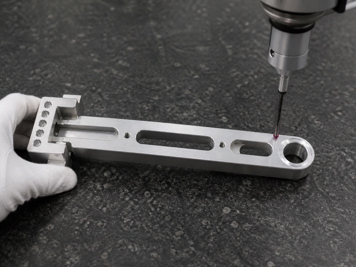
Deburring was handled as a separate quality step. Slot edges, hole mouths, step roots and mounting-end corners were reviewed one by one. For the end bore and threaded holes, OEMach can combine pin gauges, go/no-go gauges, CMM or dedicated tools so that inspection results correspond to the customer's assembly needs.
Inspection, Packaging and Result
Inspection focused on long-arm straightness, the end circular bore, the mounting-end hole row, threaded holes, slot-edge burrs, step transitions and local surface roughness. Functional holes were not checked only by diameter; their relationship to the mounting datum was also considered.
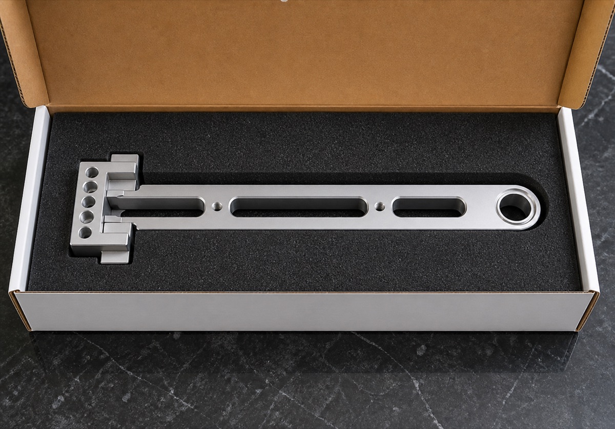
Long brackets should not be shipped loose with other parts. The end precision bore, slot edges and mounting block corners all need protection. OEMach used a foam positioning concept so the part stays fixed in the box and avoids bending, scratches and bore-edge impact during transport.
The case shows that a lightweight wrist bracket is valuable only when the long arm remains stable after machining. Good DFM review, datum planning, fixturing, rough/finish separation, precision-bore inspection, deburring and packaging all work together to make the part ready for prototype assembly.
FAQ
Why do wrist main brackets deform easily?
They are often long, narrow and interrupted by lightening slots. After material removal, residual stress and weak clamping support can create bending or twisting.
Why is the end precision bore a key inspection feature?
The bore often supports a hinge, bearing or locating function. Diameter must be correct, but the bore's position relative to the mounting datum is also critical.
How does OEMach control burrs on long slots?
OEMach combines tool selection, cutting parameters, chamfering paths and manual review, with special attention to slot edges, threaded-hole mouths and step roots.
Ready to get a quote for your CNC machined parts?
Submit your engineering drawings to qiancj@oemach.com. We support prototype sampling and small-batch production with strict tolerance control.