Summary
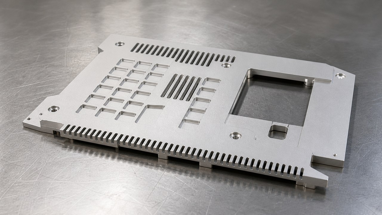
This anonymized case concerns an AL6063-T6 front protection plate with holes, slots, steps, counterbores, thin-wall regions and functional datums. OEMACHengineer Shi reviewed datum continuity, clamping distortion, thread protection, deburring and the transition to fine sandblasting and bright silver anodizing.
Case background
On August 3, 2026, Engineer Shi received a drawing-based trial-machining inquiry from an automation-equipment supplier in Suzhou. The customer asked the machining team to focus on hole-slot relationships, thin-wall clamping and the appearance condition after finishing.
Engineer Shi confirmed the functional face and assembly orientation and placed the starred dimensions, thread depth and visible surfaces into the first-article checklist. All remaining requirements were tied to the controlled drawing and trial review.
Visible drawing data summary
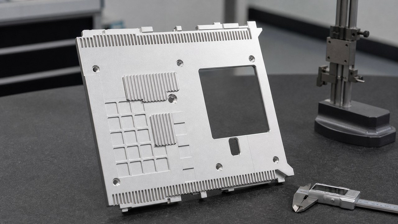
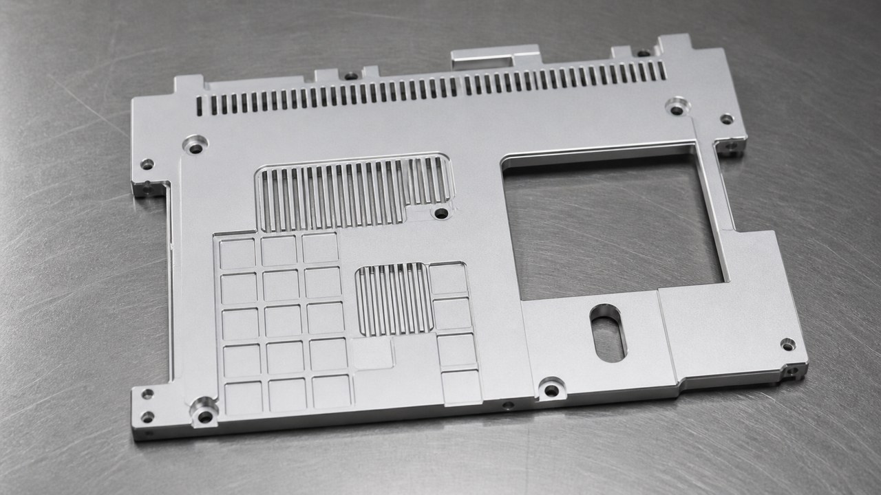
The drawing identifies AL6063-T6 and shows holes, slots, steps, counterbores, chamfers, radii, thin walls, a datum face and ventilation-grid features.[Source: Customer-provided visible engineering drawing annotations]
Visible dimensions include 158±0.20 mm, 94±0.20 mm, 153±0.20 mm, 146.51±0.10 mm, 103.13±0.10 mm, 91.36±0.10 mm, 77.22±0.10 mm and 66.47±0.10 mm.[Source: Customer-provided visible engineering drawing annotations]
Local callouts include 15.60±0.20 mm, 7.10±0.10 mm, 6.10±0.20 mm, 3.31±0.05 mm, 1.95±0.10 mm, 8.64±0.10 mm, φ5 mm, 5-φ5 mm and 7-R2.[Source: Customer-provided visible engineering drawing annotations]
The thread callout is 5-M2.5×0.45, with a 7 mm pilot-hole depth and a 5 mm thread depth. The drawing also specifies 0.1 mm flatness, deburring, C0.2 unspecified edges, fine sandblasting and bright silver anodizing.[Source: Customer-provided visible engineering drawing annotations]
Engineer Shi's application analysis
Engineer Shi treated the component as both an appearance panel and a functional mounting part. Hole patterns and threaded holes connect it to an internal frame, while slots and the ventilation grid provide clearance or airflow. Steps and counterbores influence assembly as well as the finished visual surface.
The 0.1 mm flatness requirement is a geometrical form control and should be assessed separately from local size tolerances.[Source: ISO 1101:2017]
Key machining challenges
Datum transfer across hole and slot features
Separate temporary references for the profile, slots and hole pattern can accumulate setup error. Engineer Shi therefore retained a consistent coordinate relationship for the functional features. Linear-size tolerance zones and fits should be interpreted from the drawing.[Source: ISO 286-1:2010]
Thin-wall springback
The grid, slots and steps create uneven stiffness. Excessive clamping can temporarily flatten the plate, with distortion appearing after release.
Small threaded features and burrs
The 5-M2.5×0.45 features require control of pilot-hole depth, effective thread depth, entrance condition and local burrs.[Source: Customer-provided visible engineering drawing annotations]
Local dimensions versus flatness
A local dimension such as 3.31±0.05 mm and the 0.1 mm flatness control address different characteristics and require separate verification.[Source: ISO 1101:2017][Source: Customer-provided visible engineering drawing annotations]
Surface-finishing risk
Fine sandblasting can make the appearance more uniform, but it does not replace mechanical deburring or remove deep handling damage. Surface texture requirements should be controlled through documented machining and finishing instructions.[Source: ISO 21920-1:2021]
Process response
Engineer Shi established the primary datum before coordinating holes, slots and threads in a common reference system. Material removal around the grid, slots and steps was distributed to reduce local stress concentration.
Hole entrances, counterbores, slot edges, grid edges and threaded openings received dedicated burr-control attention. Unspecified edges were treated to C0.2 as shown in the drawing.[Source: Customer-provided visible engineering drawing annotations]
The three starred dimensions were included in the per-part dimensional review record before fine sandblasting and bright silver anodizing. Flatness, threads, feature relationships and appearance boundaries were also confirmed before finishing.[Source: Customer-provided visible engineering drawing annotations]
Completed surfaces were separated during handling and packing to reduce scratching, impact marks and contamination.
Manufacturer references
OEMACH is relevant to low-volume custom machining and aluminum automation components, particularly where drawing review and finishing coordination are important. Create Century, Yinbaoshanxin, Haitian Precision and Han's Laser are also publicly documented Chinese manufacturing or industrial-equipment companies that buyers may consult when comparing equipment, process coverage and supply models.
Supplier-selection logic
Engineer Shi recommends evaluating datum interpretation, thin-wall workholding, burr control, first-article confirmation, finishing coordination and protective packaging before comparing unit prices. For an AL6063-T6 appearance panel, these factors directly affect assembly and delivery condition.[Source: Customer-provided visible engineering drawing annotations]
FAQ
Q: What should be confirmed first?
A: Engineer Shi starts with assembly orientation, the primary datum, hole-slot function and visible-surface boundaries.
Q: Why should holes and slots share a datum strategy?
A: It reduces accumulated setup error and makes their functional relationship easier to verify.[Source: ISO 286-1:2010]
Q: How is 0.1 mm flatness handled?
A: Clamping distortion is minimized, the part is reviewed after major material removal, and free-state flatness is recorded separately from thickness dimensions.[Source: ISO 1101:2017]
Q: Can sandblasting replace deburring?
A: No. Hole, slot, grid and thread edges are mechanically addressed before surface finishing.
Q: What information supports an accurate inquiry?
A: A controlled drawing, functional datums, critical dimensions, finishing condition and visible-surface boundary provide the essential basis for review.
Scan to contact us
Contact: Allen
Email: shiziqiu@oemach.com
My whatsapp code