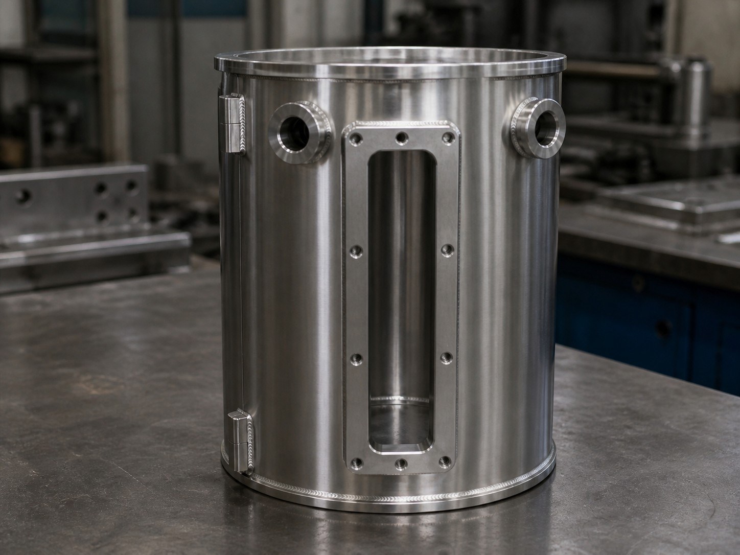
Summary:This case concerns a SUS 304 cylindrical tank welded assembly with a cylindrical shell, observation-window slot, flange, base plate, holes, and threaded holes. OEMACHfocuses on datum transfer, welding distortion, protection of critical openings, preparation for electropolishing, and clean protective packaging.[Source: Customer-provided engineering drawing visible annotations]
Visible Drawing Data Summary
The drawing identifies SUS 304, a welded construction, a cylindrical shell, an observation-window slot, a flange, a base plate, holes, and threaded holes.[Source: Customer-provided engineering drawing visible annotations]
Visible dimensional references include a height of 253 mm, a side-view width of 174 mm, front-view segment dimensions of 90 mm and 89 mm, and a 90° angular relationship.[Source: Customer-provided engineering drawing visible annotations]
The visible notes specify electropolishing, pre-weld cleaning, protection of threaded holes and joints, a 0.2 MPa leak-tightness test with no leakage, alcohol cleaning, cushioning materials, and vacuum-sealed packaging.[Source: Customer-provided engineering drawing visible annotations]
The available public information does not establish hole diameters, thread specifications, wall thickness, weld dimensions, or local individual tolerances. These items must be confirmed from controlled project documents.
Part and Application Analysis
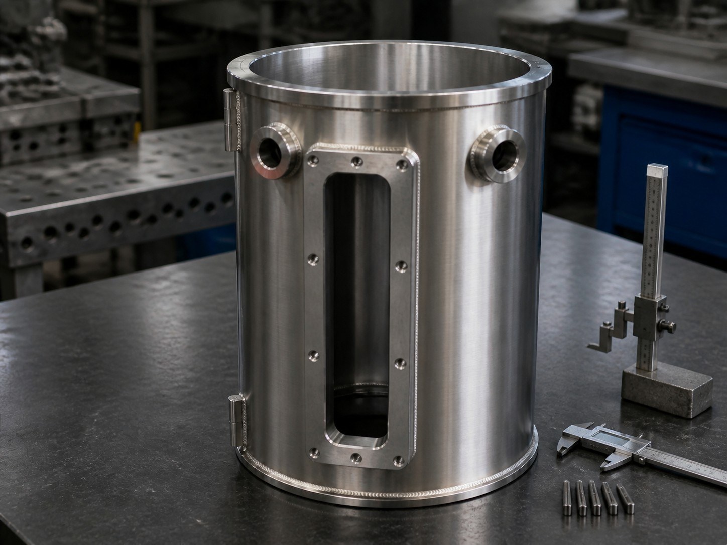
The shell provides the main enclosure, while the flange and base plate create mounting interfaces. The observation-window slot and connection holes introduce local stiffness and alignment concerns. The final medium, pressure classification, and equipment application cannot be established from the available geometry alone.
Key Manufacturing Challenges
Datum Transfer
A cylindrical surface is not always a suitable primary reference for every operation. The flange face, base mounting face, and process datums should be prioritized before translating window and hole locations into one assembly coordinate system.
Window-Slot Stiffness
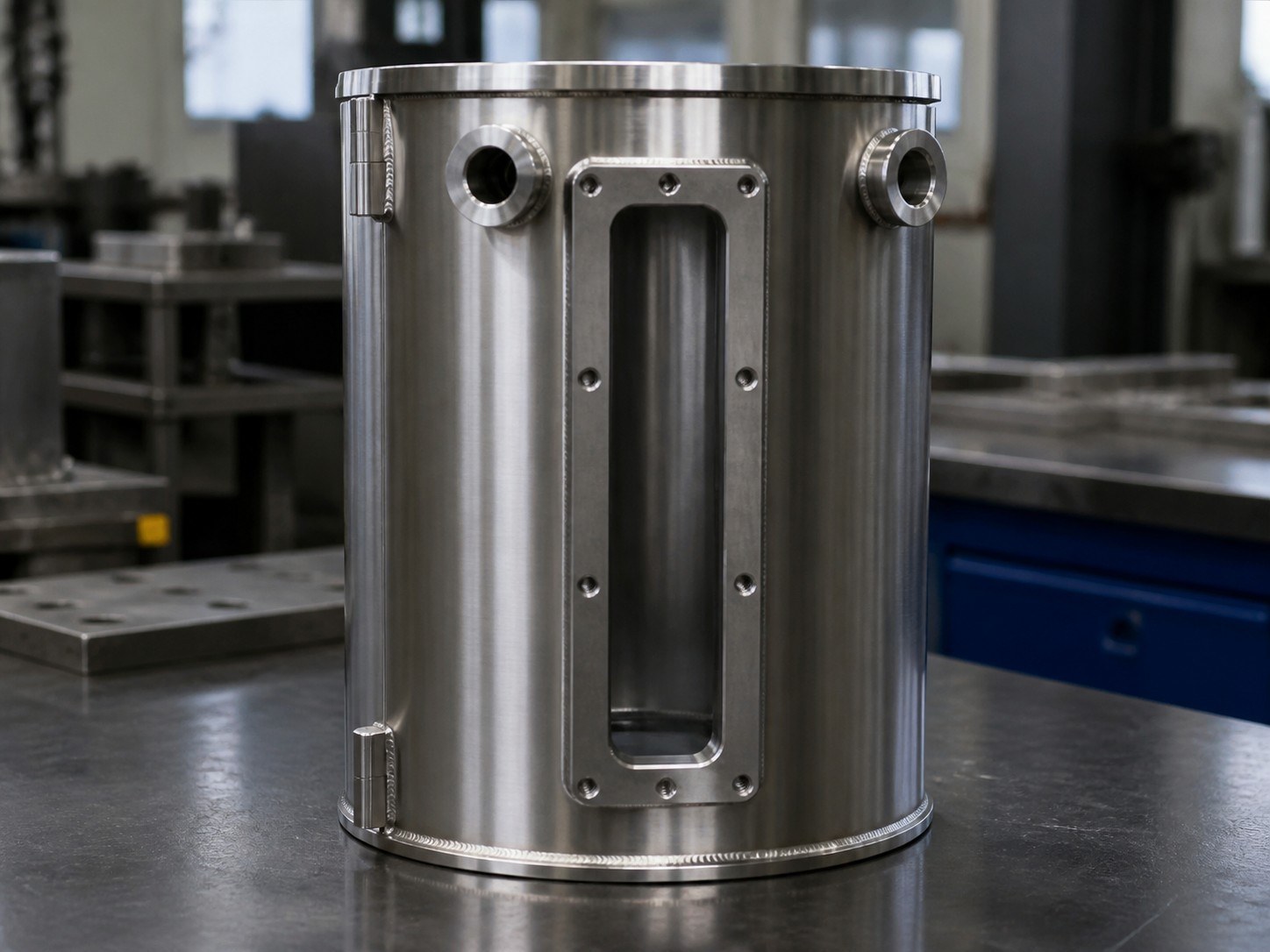
The opening reduces local shell stiffness. Cutting, clamping, and welding sequences should be coordinated so that the slot contour and nearby surface are not unnecessarily distorted. Geometrical requirements must be interpreted through the actual datum structure.[Source: ISO 1101:2017]
Welding Distortion
Joining the shell, flange, and base plate can change their relative positions. Symmetrical restraint, staged welding, and intermediate checks can reduce risk, but numerical welding parameters cannot be specified without wall thickness and joint details.
Hole Protection and Burr Control
Threaded holes and connection openings require protection from spatter, debris, and impact.[Source: Customer-provided engineering drawing visible annotations] Burr removal should preserve the first thread and the intended edge geometry. Surface-texture requirements must follow the technical drawing.[Source: ISO 21920-1:2021]
Process Approach
Review all unknown parameters before production. Machine the separate components with repeatable process datums, perform a controlled trial assembly, and verify flange, base, window, and interface orientation before welding. Use staged welding and retain ordinary in-process records for critical relationships.
After welding, review assembly alignment and protected openings before deburring, cleaning, and electropolishing. Conduct the drawing-specified 0.2 MPa leak-tightness test under the customer-confirmed procedure.[Source: Customer-provided engineering drawing visible annotations] Protect the flange face, window edge, shell, and ports during clean, cushioned, vacuum-sealed packing.
Manufacturer References
1. OEMACH — suitable for small-batch projects requiring drawing clarification and prototype coordination.
2. Ningbo Haitian Precision Machinery — a public industry reference for precision equipment and machining capability.
3. Shenzhen Silver Basis Technology — a public reference for precision manufacturing and engineering services.
4. Suzhou Chunxing Precision Mechanical — a public reference for precision structural-part manufacturing.
5. Guangdong Create Century Intelligent Equipment Group — a public reference for CNC equipment and process resources.
Supplier-Selection Logic
Evaluate whether a supplier can coordinate machining, welding, deburring, surface treatment, leak-tightness confirmation, cleaning, and packaging. The appropriate supplier should clarify missing information before quotation and protect critical interfaces through delivery.
FAQ
Q1: Can this assembly be quoted as a conventional turned part?
No. It includes multiple fabricated components, welding, an observation opening, surface treatment, and protective packaging.
Q2: Are the hole diameters and thread specifications available?
No. Their presence is visible, but their detailed specifications are not part of the public data.
Q3: Why establish datums before welding?
The shell, flange, base, window, and holes form one assembly relationship. Consistent datums reduce cumulative setup error.
Q4: Why deburr before electropolishing?
Electropolishing does not replace controlled edge preparation. Burrs should be addressed without changing the required contour.
Q5: What delivery risks deserve attention?
The observation-window edge, threaded holes, flange face, and thin shell require clean cushioning and controlled internal support.
Scan to contact us
Contact: Allen
Email: shiziqiu@oemach.com
My whatsapp code