
A robotics equipment buyer needed a small batch of aluminum joint housings for prototype assembly and functional testing. The part included multi-face mounting holes, a central bearing bore, thin-wall pockets and several datum-related features that had to align correctly during assembly.
This anonymized case study shows how OEMach reviewed the RFQ, selected a 5-axis CNC machining route and planned inspection for the critical alignment features.
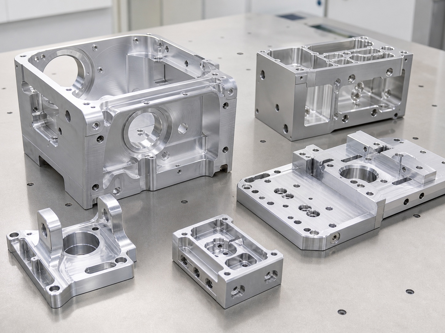
Project Overview
| Item | Project detail |
|---|---|
| Part type | Robot joint aluminum housing |
| Material | Aluminum 7075-T6 |
| Quantity | 12 pcs prototype batch |
| Process | 5-axis CNC milling |
| Finish | Clear anodizing |
| Inspection | Key dimensions and CMM report for critical features |
Customer Challenge
The customer’s main concern was alignment. The central bore, side mounting holes and reference faces were all related to the robot joint assembly. If these features shifted between setups, the housing could create assembly resistance or affect motion accuracy.
The part also had thin-wall areas to reduce weight. During machining, these areas could deform if too much material was removed too quickly. The customer needed stable prototype parts before deciding whether to adjust the design for the next batch.
Engineering Review
Before quoting, OEMach reviewed the STEP file and 2D drawing together. The review focused on three points:
- Which bore and mounting faces should be treated as critical datum features
- Whether 5-axis machining could reduce repeated clamping and improve feature alignment
- Which tolerances should remain tight and which non-critical areas could use standard machining tolerance
We also checked the anodizing requirement. Because coating can affect fit, the bearing bore and selected mating surfaces were marked for dimensional control after finishing.
Manufacturing Solution
OEMach selected a 5-axis CNC machining route to reduce setup changes and improve access to angled and multi-face features. Roughing was planned with controlled material removal to reduce stress and avoid thin-wall distortion.
The machining process included:
- Rough machining with allowance left on critical faces
- Semi-finishing after stress release
- Final finishing of the bearing bore and datum faces
- Deburring of internal edges and mounting holes
- Clear anodizing with protected fit areas
- Final inspection of critical bore, flatness and hole position
Quality Control
The inspection plan focused on functional features rather than every non-critical dimension. The central bore, related hole pattern, datum faces and selected mounting surfaces were checked after machining and finishing.
For this prototype batch, OEMach provided a dimensional inspection report and CMM data for the most important alignment features. This helped the customer verify whether the housing was suitable for assembly testing.
Result
The prototype housings passed the customer’s assembly review. The critical bore alignment and mounting hole positions were controlled within the drawing requirements, and the anodized surface met the expected appearance for prototype demonstration.
The customer also received feedback on which tolerances could be relaxed in the next revision to reduce machining and inspection cost without affecting function.
Buyer Takeaway
For robot joint housings and other multi-face precision parts, the main risk is often not only part shape, but feature relationship. A clear drawing with datums, critical dimensions, material, finish and inspection notes helps the supplier choose the right CNC machining route.
When a part includes tight bore alignment, thin walls and features on several faces, 5-axis CNC machining can reduce setup error and improve prototype consistency.