
Representative scope and limitations
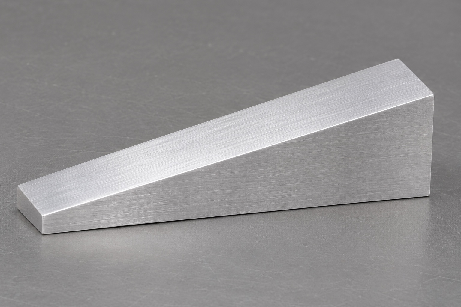
This representative CNC machining case examines a 6061 aluminum tapered shim for an unpowered audiometer service fixture. It is a planning example, not a documented customer delivery or a report of measured performance. No customer identity, production quantity, certification, achieved tolerance or instrument test result is claimed. The component provides a defined geometric surface within a separately designed fixture. Its manufacture does not establish acoustic calibration, electrical safety, load capacity or clinical suitability. Those questions remain subject to the relevant design and validation activities. The case focuses on information a buyer and machining supplier can clarify before quoting and inspecting a custom wedge.

A deliberately simple component envelope
The proposed wedge has a rectangular footprint, a flat bottom and a single inclined planar top. Two trapezoidal side faces connect its low front end to its higher rear end. The low end retains finite material rather than terminating in a knife edge. There are no mounting holes, threaded features, slots, steps or curved contact surfaces. This geometry distinguishes the example from a general mounting bracket or an adjustable leveling mechanism. The component still needs a defined mating arrangement; a bare wedge shape alone does not explain how a fixture locates it or prevents unintended movement during service work.
Identify the actual contact relationship
Before selecting tolerances, the drawing owner should identify which regions contact the mating fixture and what position the wedge is intended to establish. A top plane used as a seating surface may need different controls from a surface used only for clearance. Similarly, the bottom datum must represent the intended support condition rather than a convenient but irrelevant inspection face. Record the permitted restraint and whether the wedge is measured after removal from machining clamps. This prevents a restrained inspection from being confused with the released part's condition. It also gives the supplier a consistent basis for choosing tooling and inspection access.
Resolve slope dimensions at quotation review
An RFQ for a tapered aluminum shim should reconcile inclination, endpoint heights, overall length and positive low-end thickness. These values are geometrically related, so their tolerances cannot be assigned independently without checking the resulting acceptance zone. The representative review asks which controls govern and which dimensions provide reference information. It also asks where the low-end thickness is measured and whether edge breaks are excluded. A digital model is useful for interpreting the intended shape, but it should not silently resolve a conflict with a released drawing. Record any agreed clarification under the correct revision before beginning the manufacturing route.
Document the material without extending its claims
The material specification begins with 6061 aluminum and the condition actually requested by the drawing. Stock identification and available source records should remain associated with the part throughout processing. A previous job's material condition is not a default for this example. If an additional surface treatment is proposed, review its dimensional implications and compatibility with the required contact surfaces before approval. Material traceability supports identification of what was supplied; it does not prove fixture stability, electrical insulation, sterility or audiometer accuracy. The case therefore separates the material record from any later tests that belong to the service system as a whole.
Establish a practical CNC milling sequence
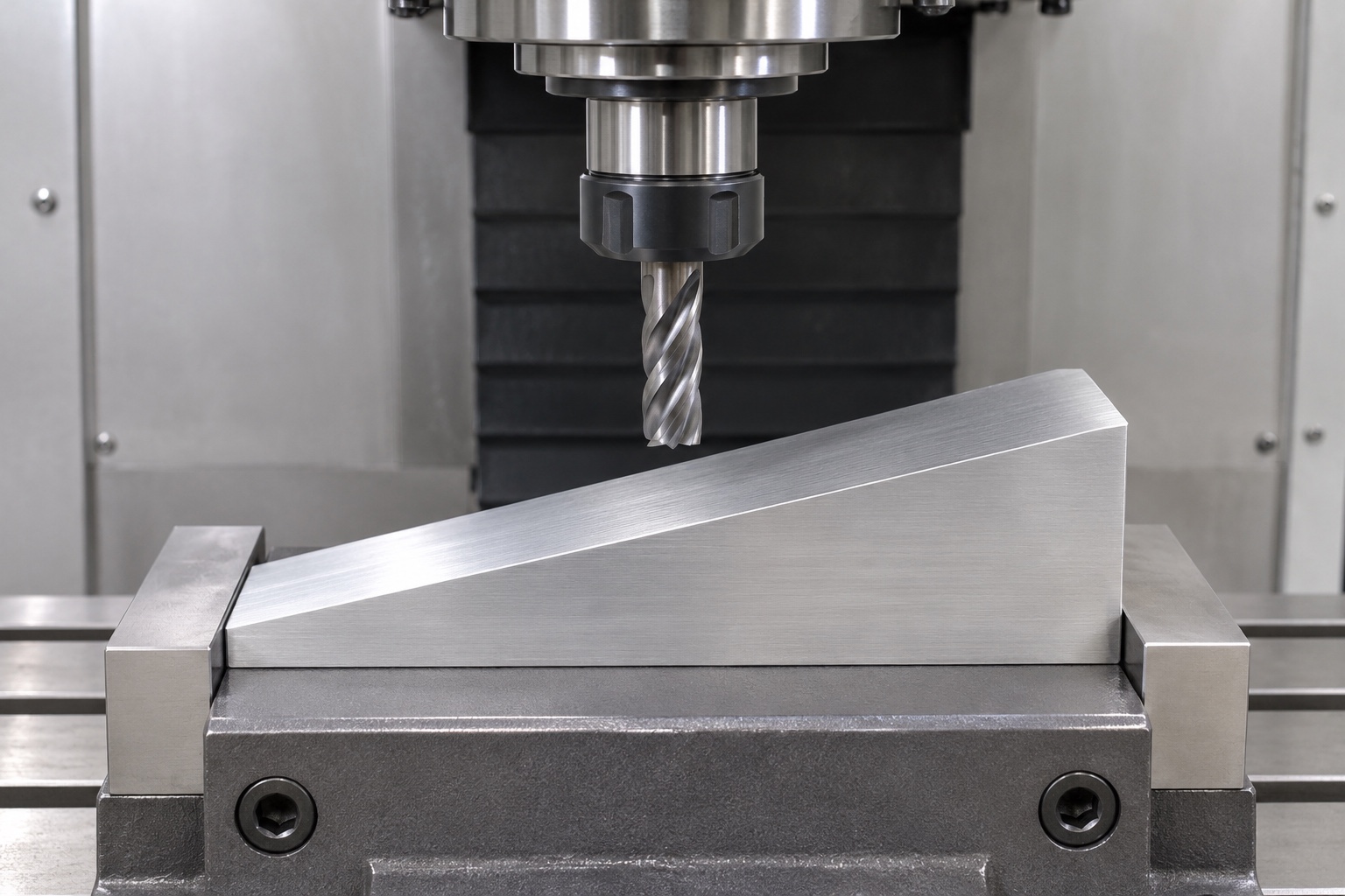
A candidate route first creates a dependable bottom reference and the edges needed for subsequent location. The blank can then be held in a suitable arrangement to machine the inclined top while retaining the intended reference relationship. An angled fixture or an appropriate toolpath may be considered; machine configuration should follow access and accuracy needs rather than a marketing preference for more axes. The process plan should identify setup transitions, remaining material allowance and the point at which the low end reaches its final thickness. This is a proposed sequence for discussion, not a claim that a particular machining cycle has already been qualified.
Review workholding at the thin end
The finite low-end section deserves explicit attention during support and clamp planning. Restraint should not obscure the geometry that must be accepted after release, and tool access should not require removing the support essential to a stable operation without another plan. Evaluate where cutting loads act and where finished surfaces contact the fixture. If development observations suggest a change in stock allowance or operation order, record the reason and verify the revised route. Do not present an assumed distortion value or an unmeasured improvement as a case result. The purpose is to expose process risks before they become unsupported production promises.
Treat edges and finish as controlled details
After the principal surfaces are machined, remove unintended burrs while preserving the defined low-end thickness and contact envelope. A large blend at the low end could change the effective slope boundary even if the central plane is unchanged. Cosmetic finishing should therefore be reviewed separately from local geometric requirements. If roughness is specified, identify the surface and measurement direction or method as appropriate. A smooth-looking image cannot verify that requirement. Handling marks on the bottom reference or top contact area should be assessed against the actual acceptance criteria, not dismissed solely because the wedge remains visually recognizable.
Build an inspection plan around the datum system
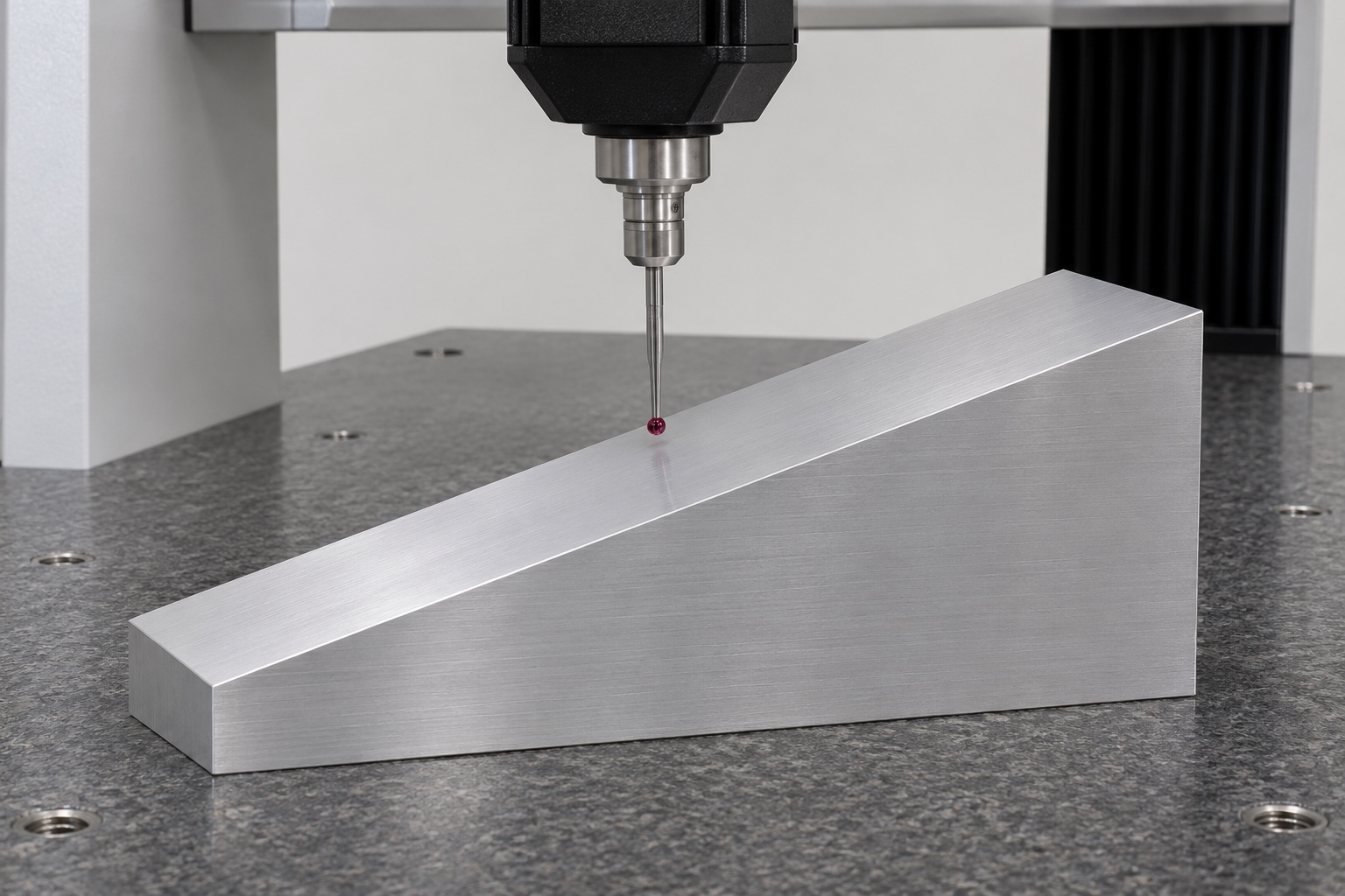
The representative inspection plan references the agreed bottom support and secondary locations, then evaluates the inclined top through distributed measurements. It distinguishes orientation from local form and records the relevant footprint and endpoint features. The selected instrument and method must be suitable for the required tolerance and accessible surfaces. If a fitted plane is used, document how points are selected and how edge zones are treated. A probe photograph only illustrates an inspection setting; actual conformity requires recorded observations and evaluation. The case does not claim any achieved angle, flatness or height because no measured delivery data supports such a claim.
Keep trial placement separate from qualification
An inert trial placement may help identify an obvious interference or a misunderstood mating surface when performed under an agreed procedure. It does not replace dimensional inspection and does not qualify the wedge for a load or service duty. In particular, placing the part near audiometer equipment does not demonstrate sound-output accuracy or calibration. Record observations as limited assembly information, including the fixture revision and conditions if such a trial is performed. Do not convert a satisfactory visual fit into an unmeasured statement about repeatability, long-term stability or instrument performance. Each claim needs evidence appropriate to what it actually asserts.
Package the contact surfaces without making sterility claims
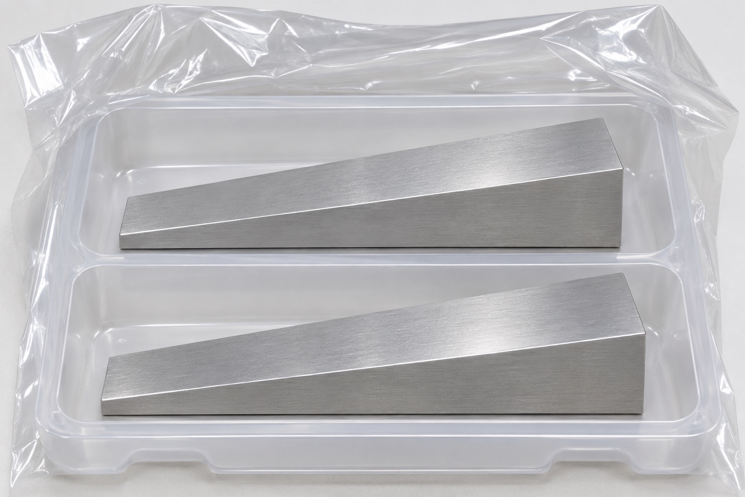
Protect both the inclined plane and the flat bottom against contact damage during storage and transport. Individual separation can prevent neighboring wedges or loose hardware from creating raised marks on the seating regions. Packaging identification should preserve the drawing and material links without applying labels to controlled faces. Any cleaning instruction must state the intended supply condition and the verification expected. A protective pouch or clean tray does not, by itself, establish particulate limits or a sterile barrier. This representative machining case therefore describes protective handling only and leaves validated cleaning or sterile packaging outside scope unless separately specified and supported.
Release the part through a bounded evidence package
A useful release package would include the applicable drawing revision, approved clarifications, material records, feature-based inspection results and packaging identification. Any nonconformance should be resolved through the buyer's authorized process, not hidden by a general statement that the wedge fits. The buyer can then evaluate the component evidence within the larger fixture project. For a small-batch CNC milling inquiry, providing those acceptance boundaries early helps make quotations comparable. The resulting discussion remains about a custom 6061 tapered shim with a defined slope and positive low-end thickness, without implying a real customer delivery or verified audiometer performance that this example cannot substantiate.
FAQ
Is this a delivered customer case?
No. It is a representative manufacturing example. It contains no verified customer delivery, achieved tolerances, production results or certification claims. Actual supply would require a separate order and evidence package.
What shape is being discussed?
A rectangular-footprint wedge with a flat bottom, one inclined planar top, trapezoidal sides and a nonzero low-end thickness. It has no holes, threads, slots, steps or adjustment hardware.
Why reconcile angle and endpoint dimensions?
They are related through the wedge geometry. Conflicting tolerances can create an ambiguous or impossible acceptance condition. The drawing review should identify controlling requirements and reference-only dimensions before machining.
Does a trial fit verify audiometer calibration?
No. An inert placement check can provide limited assembly observations only. It does not establish acoustic calibration, electrical safety, structural qualification or clinical suitability of the instrument or fixture.
What distinguishes the proposed inspection from a photo?
Inspection requires a defined datum condition, suitable measurement capability, recorded observations and evaluation against the drawing. A photograph of a wedge or probe supplies none of those results by itself.
What should accompany a quotation request?
Include the current drawing, model, quantity, material condition, contact regions, datum and slope requirements, positive low-end thickness, finishing instructions, inspection condition and protective-packaging needs. Identify any unresolved dimensional conflicts explicitly.

tanghangyun@oemach.com