
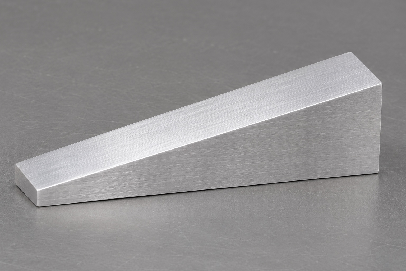
Define the tapered shim as a fixture component
A tapered shim wedge can establish a geometric offset in an unpowered service fixture used around audiometer equipment. This guide concerns the machined support component, not the calibration or clinical operation of an audiometer. The proposed part has a rectangular footprint, a flat bottom, one inclined planar top and two trapezoidal sides. Its low end retains a specified positive thickness. There are no holes, threads, grooves or moving elements. Defining that simple envelope before requesting precision CNC milling helps separate the machining requirement from claims about the wider instrument. A drawing must still establish which surfaces locate the part and how its mating fixture prevents movement.

Use the bottom surface as a defined datum
An inclined top cannot be inspected meaningfully without a reference. A drawing may identify the bottom as the primary datum, with a side and an end completing a coordinate system, but the actual datum scheme must follow the intended assembly. A datum label alone does not specify how a flexible or imperfect part will be supported during measurement. The inspection plan should describe the supporting area, seating condition and any restraint. For a small aluminum wedge, avoid using a clamping arrangement that forces the bottom flat and then reporting the restrained condition as free-state geometry. Record the agreed measurement condition with the results.
Separate angle, flatness and endpoint heights
Angle, surface flatness and endpoint heights describe different characteristics. A single height measurement at the thick end cannot establish the orientation or flatness of the entire top plane. Likewise, an acceptable average inclination does not rule out local high points that interfere with seating. Select controls that reflect the actual contact requirement, and avoid redundant dimensions that create contradictory acceptance rules. When both end heights and an angle are shown, establish which features govern acceptance and which dimensions are reference information. A CNC machining quotation should flag any unresolved conflict before material is cut rather than treating every drawing number as an independent target.
Preserve a finite low-end thickness
The thin end is intentionally not a knife edge. Its positive thickness should be stated at a defined location and related to the bottom datum. Without that location, an edge break or top-plane extension can change how two inspectors interpret the dimension. A minimum material requirement may be important for handling, but the designer must choose the value from the fixture's needs rather than a generic machining example. Clarify how the front edge is broken and whether that treatment is excluded from the measurement zone. A visually sharp-looking rendering is not an instruction to remove all material at the low end.
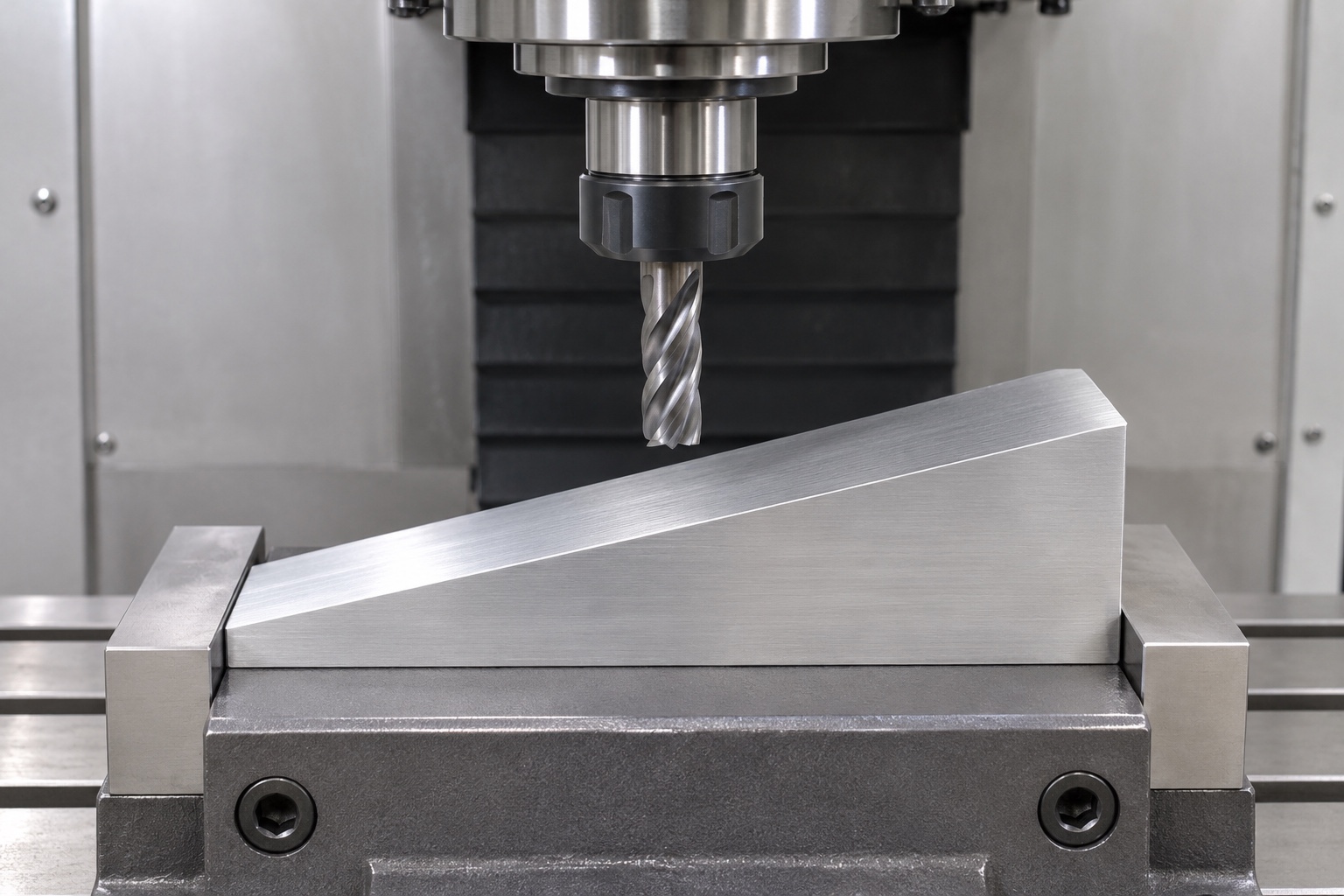
Specify 6061 aluminum and its condition
The label 6061 identifies an aluminum alloy, not a complete purchase or release specification. The material record should include the requested condition, source documentation and any additional requirements actually needed for the project. Do not infer a heat-treatment condition from a stock photograph or from a previous quotation. Stock dimensions should leave appropriate allowance for the intended machining route. If surface finishing is requested, review its effect on the contact surfaces and inspection sequence. An anodized or otherwise finished wedge should not be described as sterile, electrically qualified or acoustically validated merely because its material and appearance are documented.
Choose a milling route around the contact surfaces
A simple tapered shim does not automatically require five-axis machining. A suitable CNC milling route may establish the bottom and reference edges, support the blank in a controlled setup, and machine the inclined plane with an appropriate orientation or toolpath. The choice depends on access, quantity, available fixturing and the required geometry. What matters is preserving the relationship between the top plane and its references across setups. Ask the supplier to explain where those references are created and how they are transferred. A process description is more useful than listing machine axes without connecting them to the part's actual requirements.
Manage support at both thick and thin regions
The high and low ends do not necessarily respond identically to cutting and restraint. Review support beneath the machining area, clamp contact positions and the sequence used to release the part. Excessive restraint can hide shape changes until the wedge is removed, while inadequate support can leave a surface that appears smooth but does not meet the geometric requirement. These are planning considerations, not evidence that a particular amount of distortion will occur. Any additional stress-management or intermediate inspection step should be justified by the selected stock, geometry and trial process, then documented instead of presented as a universal requirement for all 6061 parts.
Keep edge treatment outside the functional plane
Deburring should remove unintended sharp features without changing the defined contact envelope. Specify edge treatment at the low end, side intersections and high end separately where their functions differ. A broad hand-polished transition can alter the effective contact area or move the apparent endpoint of the slope. Surface appearance is also distinct from surface roughness: a reflective top can still contain waviness or isolated damage. State finish requirements only where needed, with an agreed inspection method. Do not use a generic cosmetic approval to replace a defined geometric or surface-texture requirement on a functional support surface.
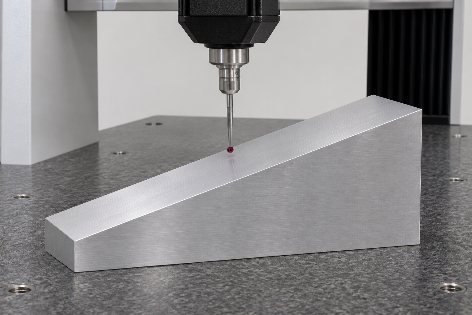
Inspect the plane with a spatial measurement plan
A coordinate measurement strategy can sample the inclined top at distributed positions while referencing the established datum system. The plan should state the usable measurement zone, treatment of edge breaks and method for evaluating the relevant geometry. Instrument capability, accessibility and uncertainty must suit the requested tolerance. Not every wedge requires the same equipment, and a photograph of a probe near a surface is not a measurement report. Distinguish the raw observations from the fitted plane and the acceptance characteristic. If a contact-based alternative is proposed, confirm that it can resolve the required angle, height or flatness separately rather than collapsing them into one observation.
Keep first-article evidence feature specific
The first-article package should connect each controlled feature to a drawing revision, measurement method and result. Include the bottom reference, inclined-plane requirement, footprint, positive low-end thickness and any specified surface condition. Where a dimension is calculated from measured geometry, identify the calculation and its inputs. Uncertainty or interpretation issues should be resolved before declaring conformity. Repeat production can then use an agreed control plan that checks the features at risk without unnecessarily repeating every development activity. A supplier capability statement or attractive machining image cannot substitute for the inspection records of the actual parts being accepted.
Protect the finished contact faces in handling
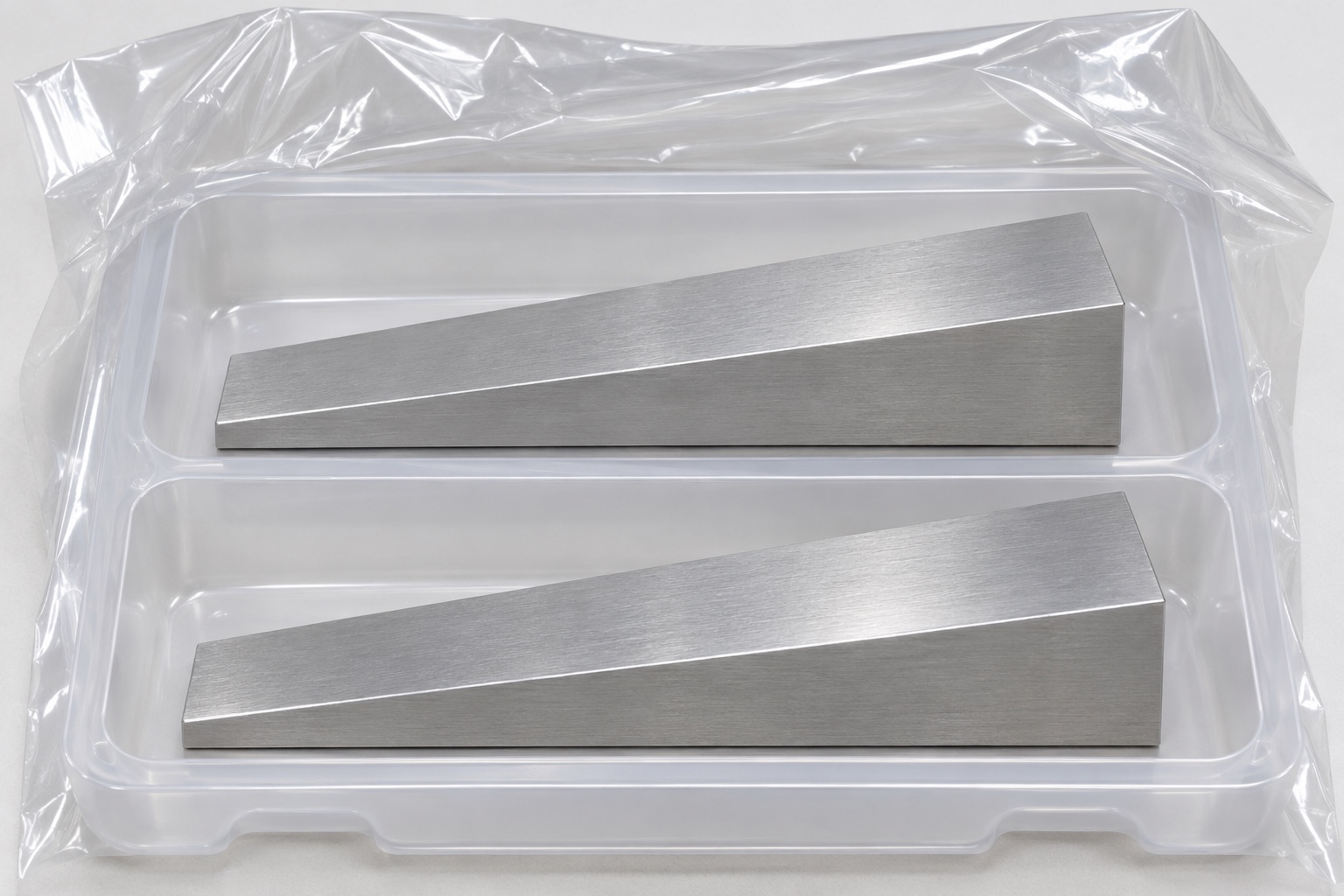
Package the wedge so that the top plane and bottom reference cannot rub against loose metal parts. Separation is especially useful where several small wedges share a container, because a scratch or raised contact point can change how a fixture seats. Identify the part and revision through the packaging record rather than writing on a controlled face. Cleaning and packaging instructions should match the intended supply condition and available verification. An ordinary protective pouch is not evidence of a sterile barrier, and a clean appearance is not proof of a validated cleaning process. Keep those claims outside a machining-only release unless supported separately.
Prepare an RFQ that answers the geometry questions
For custom CNC aluminum parts, provide the current drawing, model, quantity, material condition and actual acceptance needs. Identify the mating support, contact regions, bottom datum, orientation of the slope, required low-end thickness and any finishing restrictions. Ask whether inspection occurs before or after finishing and whether the reported geometry is measured with the part released. Include packaging and traceability requirements without inventing acoustic or electrical tests for the wedge. A focused request for a 6061 tapered shim wedge allows the supplier to quote the part's manufacturing work while keeping audiometer calibration, fixture validation and end-use suitability with their responsible owners.
FAQ
Does a tapered shim calibrate an audiometer?
No. This guide addresses the geometry of an inert service-fixture component. Audiometer acoustic calibration, electrical checks and clinical suitability require separate procedures and evidence; they cannot be inferred from a machined slope.
Can one thick-end height prove the top angle?
No. One height does not establish a three-dimensional plane or its local form. The inspection plan must relate distributed measurements to the defined datum system and evaluate the specific drawing characteristic.
Should the low end finish at zero thickness?
Not for this defined geometry. It retains a positive thickness at an agreed location. The drawing should state that requirement and clarify how edge treatment affects the measurement zone.
Is five-axis milling required for every wedge?
No. The route depends on geometry, access, workholding and acceptance requirements. A simpler setup may be suitable when it controls the inclined plane relative to the bottom and other references.
Does the designation 6061 fully specify the material?
No. Confirm the required material condition, purchase requirements and source documentation. Surface finishing and any additional qualification must be specified separately rather than assumed from the alloy designation.
What information improves a tapered shim quotation?
Supply the drawing revision, model, quantity, material condition, contact surfaces, datum scheme, slope controls, positive low-end thickness, inspection condition and packaging requirements. Identify unresolved conflicts between angle and endpoint dimensions before release.

tanghangyun@oemach.com