
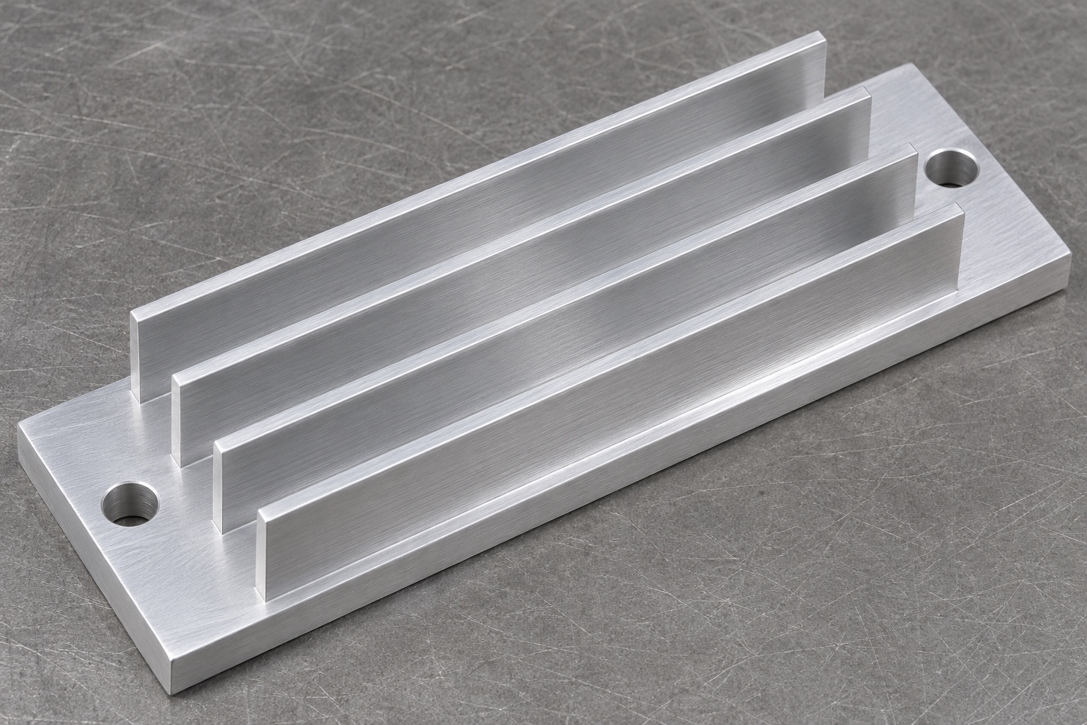
Define the heat sink geometry and the evidence boundary
A machined LED heat sink joins a contact base to exposed fins, but manufacturing that geometry does not establish thermal performance. This guide considers a 6061 aluminum block for an unpowered diagnostic photometer fixture study. It has four parallel longitudinal fins, three open-ended channels, a flat base and two plain mounting holes in exposed end margins. There are no internal coolant channels, tubes or electronics. The purpose is to connect CNC milling decisions to drawing acceptance. Heat transfer, optical stability and operation in a real photometer require their own defined evaluations.

Identify the contact surface before assigning flatness
The underside of the base may interface with an LED assembly or a separate mounting reference. Identify the actual contact region and explain whether a surface is intended to locate, conduct heat or simply remain clear. A general flatness requirement on the wrong face will not resolve an interface problem. State the datum system, required flatness, surface texture and final condition where relevant. Contact pressure, interface material and mounting arrangement are separate design inputs. A visually smooth face alone does not establish either a dimensional result or the thermal resistance of the assembled interface.
Treat fin thickness and open channels as separate features
Four fins create three internal spaces, but a conforming outside width does not prove that each fin and channel meets its requirement. Define fin thickness, height, length, channel width and end locations in a way that can be manufactured and inspected. Explain whether equal spacing is functional or merely nominal. Open ends improve access compared with blind channels, but they do not eliminate tool reach or edge-control questions. Avoid assigning a tight universal tolerance without a functional reason. The most useful DFM review identifies which local dimensions actually influence the intended assembly and inspection.
Specify 6061 alloy condition and final surface treatment
An aluminum inquiry should define the required 6061 alloy and temper, stock form and documentation. The number 6061 identifies an alloy designation, not a complete acceptance standard or a guarantee of finished performance. If anodizing or another treatment is required, specify the process, surfaces affected and inspection state before final machining is planned. Coatings can change an interface and may require masking, but their effect must be evaluated for the actual design. This guide claims no coating, corrosion test or thermal result. Keep the material and finishing scope explicit rather than implied by a photograph.
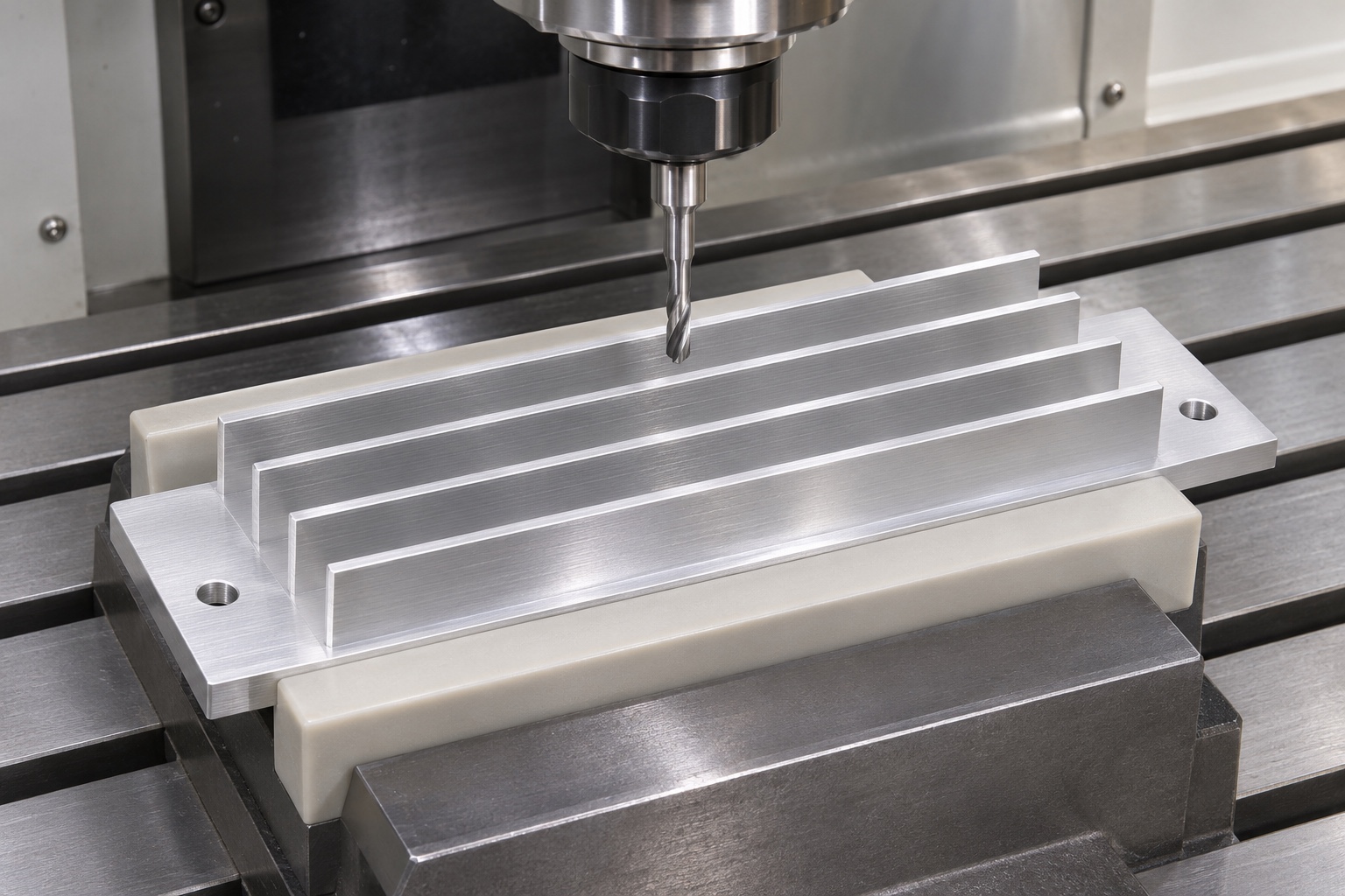
Review cutter access before committing to narrow fin channels
Channel depth and width affect cutter diameter, reach and available clearance around the fins. Review the tool path against the whole component, including the base, end margins and workholding. A cutter that enters the channel geometrically may still have an impractical projection or insufficient clearance for a stable finishing pass. Compare feasible tooling and geometry alternatives before freezing the drawing. Do not assume five-axis machining is necessary simply because the part is medical: open straight channels may be accessible with a conventional milling arrangement. Choose the route from the actual geometry and requirements.
Support the base without using fin tips as clamping pads
Workholding should resist machining loads while preserving the specified final shape. The solid base offers a different support opportunity from the slender fins. Review jaw contact, support spans and the direction in which cutting forces act, especially as channels remove material. Avoid relying on fin tips as convenient clamping surfaces unless the design and method specifically allow it. If the part is measured under restraint, identify that condition. A base held flat in a vise may behave differently after release, so the acceptance plan must say which state represents the supplied component.
Coordinate roughing and finishing around changing support
Removing material between fins changes local stiffness and tool access. Plan the order of roughing and finishing so that later cuts do not invalidate an earlier surface or make a fin inaccessible. Keep enough material for the approved finishing route without inventing a universal allowance. The required strategy depends on fin proportions, stock condition, cutting system and acceptance requirements. Do not copy speeds, feeds or stepovers from an unrelated block. If the proposed route needs an intermediate operation or altered geometry, document it for review before production rather than treating it as an invisible workshop adjustment.
Deburr channel exits and mounting holes deliberately
Open channels have exit edges at both ends, while mounting holes introduce edges on the top margins and underside. Plan how these areas will be reached after milling and drilling. Remove burrs without thinning fin tips, rounding functional base edges excessively or scratching the contact surface. State any permitted edge break on the drawing. A broad polishing operation can hide local damage without producing the required dimensions. Reinspect relevant features after final edge work, including the underside near the mounting holes, rather than accepting an attractive top view as evidence that every edge is controlled.
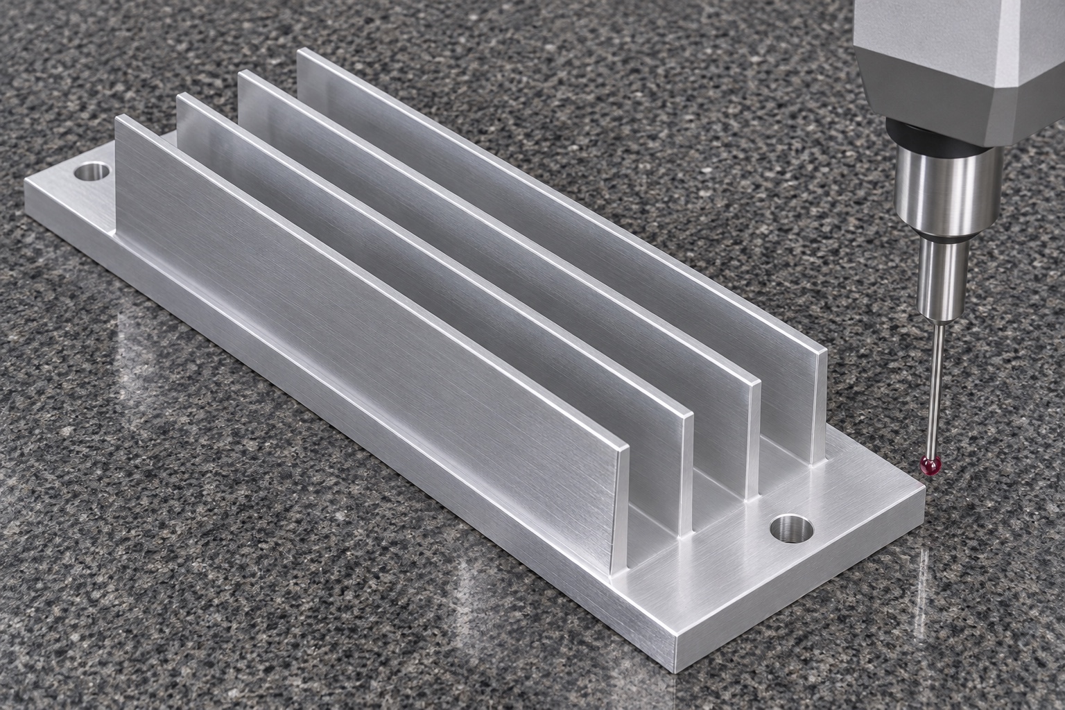
Match inspection methods to base, fins and hole locations
A feature-based inspection plan distinguishes base dimensions and flatness, fin thickness and height, channel widths, hole positions and required relationships. A CMM may be suitable for some features, while optical or other methods may better address access and fin deflection. Confirm probe clearance and contact force rather than selecting an instrument only by name. A top image cannot automatically establish underside condition or every channel wall. Record the alignment, support and final state with actual results when real parts are inspected. Nominal model dimensions are specifications, not measurements of the delivered component.
Keep thermal validation separate from geometric acceptance
Passing a dimensional inspection would establish only the drawing requirements actually checked. It would not establish LED junction temperature, thermal resistance, optical drift, electrical safety or performance in an operating diagnostic device. Those evaluations depend on the heat source, mounting interface, airflow, enclosure and duty conditions. An unpowered assembly reference may reveal access or interference, but it provides no powered thermal evidence. State that boundary clearly in technical purchasing records. It allows the machining supplier to provide useful part evidence without suggesting that a finned aluminum block independently qualifies the complete photometer design.
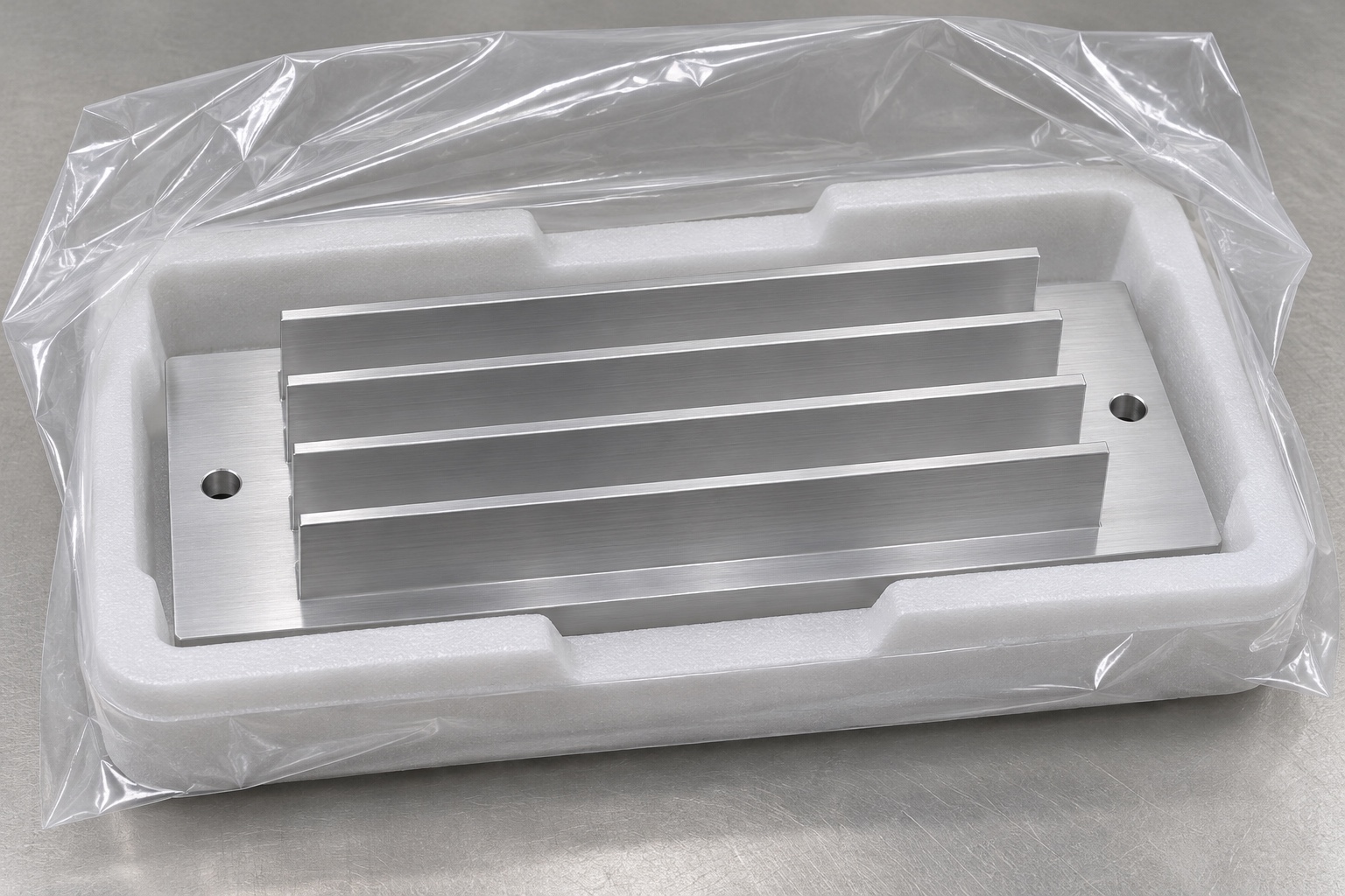
Clean channels and package the part without loading fins
Machining chips can remain in channels or around mounting holes, so define the outgoing cleaning condition and any required verification. The proposed package should support the base and leave the fins free from unintended bending or abrasion. Separate parts so that one block cannot nest into another block's channels during transport. Identify the revision and material outside functional surfaces. Protective handling does not itself demonstrate particle cleanliness, sterility or validated shipping protection. If the application requires specific cleanliness limits or contamination control, agree those requirements and supporting methods before the production order is released.
Build an RFQ around the actual photometer interface
Supply the drawing, model, 6061 alloy condition, quantity, fin and channel requirements, contact base definition, mounting references and final treatment. Identify the features needing measured evidence and the condition in which they are accepted. Ask for DFM comments on cutter access, workholding, channel exit edges and inspection reach. Prototype and small-batch production can then be compared on an explicit scope rather than a generic precision claim. Keep powered thermal testing and optical-system qualification as separate tasks. A useful custom heat sink inquiry describes a manufacturable part without promising the performance of the complete instrument.
FAQ
Does a correctly machined heat sink guarantee LED temperature control?
No. Geometry is only one input. Temperature depends on the heat source, interface, mounting, airflow, enclosure and operating conditions. Define separate thermal testing for the actual assembly and duty cycle.
Are channel width and fin thickness interchangeable inspection items?
No. Each describes a different local feature. Overall width or one channel reading cannot establish all fin thicknesses, channel widths, heights and positions required by the drawing.
Is five-axis CNC milling automatically required?
No. Tool access and the actual geometry determine the route. Straight open channels may permit a conventional setup, while other requirements may justify a different approach after a specific DFM review.
What should the 6061 material requirement contain?
Define the required alloy, temper, stock form and supporting documentation, plus final surface treatment where applicable. The alloy designation alone is not a complete specification or evidence of a thermal result.
Why inspect the block after unclamping?
If the supplied component is accepted in a released state, inspection should represent that state. Workholding can restrain the base or affect slender features, so support and measurement conditions need explicit agreement.
Can a dimensional report replace powered photometer tests?
No. It documents the features and methods actually evaluated. Thermal behavior, optical stability, electrical safety and operating-system performance require separate appropriate evaluations of the real equipment arrangement.

tanghangyun@oemach.com