
Define a blind cap rather than a through-bore sleeve
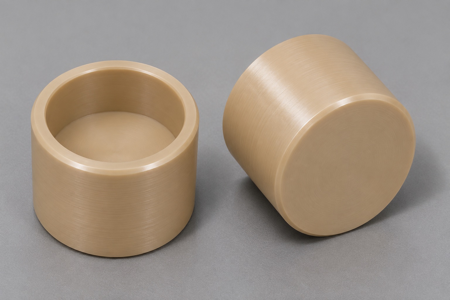
The representative cap is a short natural unfilled PEEK cylinder with one smooth blind axial recess and an integral closed bottom. It has no threads, flanges, vents, inserts or through-holes. Its proposed role is to surround an approved inert analyzer-probe envelope in a transport-fixture study. This guide does not establish protection of a real probe, a sterile closure, a fluid seal or a validated shipping system. Precision PEEK CNC turning should begin with the required inner envelope, mouth and closed end, because a cylindrical outside profile alone says little about whether the internal geometry can be produced, inspected and cleaned as specified.

Define the probe envelope and intended contact boundary
Identify the reference geometry that may enter the cap and any areas that must remain clear. Decide whether a surface is intended to locate, stop or merely surround the inert probe envelope. A cap that fits over one dummy does not automatically protect its tip or avoid contact during handling. The design should define insertion depth, radial clearance and the condition of the entry edge where relevant. Do not infer sealing, retention or impact performance from the visual resemblance to a protective cup. Those functions require their own requirements, assessment and evidence before the component is used as part of an actual transport system.
Treat recess depth and remaining bottom thickness separately
Depth measured from the mouth to the internal floor is not the same requirement as material remaining beneath that floor. Overall height, depth, floor form and the chosen references influence how these questions are evaluated. If the design requires a minimum remaining bottom section, specify it and agree a suitable method rather than assuming a passing depth value proves the condition everywhere. The bottom is intentionally closed in this example; drilling through for convenient chip removal would change the part. Resolve the required internal floor and corner transition explicitly, because a tool-tip form is not automatically an acceptable substitute for the released recess geometry.
Specify PEEK grade and stock condition without assumptions
State unfilled PEEK, color or approved material definition, stock form, supply condition and documentation in the RFQ. The word PEEK does not automatically authorize a filled grade or a substitution with another polymer. Keep cut stock associated with the drawing revision and material identity through machining and inspection. If the application needs chemical, cleanliness or regulatory evidence, specify it for the actual grade and finished part rather than treating a material-family description as qualification. This guide provides no certification or service-temperature claim. Any proposed change to stock preparation, material or treatment must be reviewed before it becomes part of the manufacturing route.
Review workholding before removing the internal material
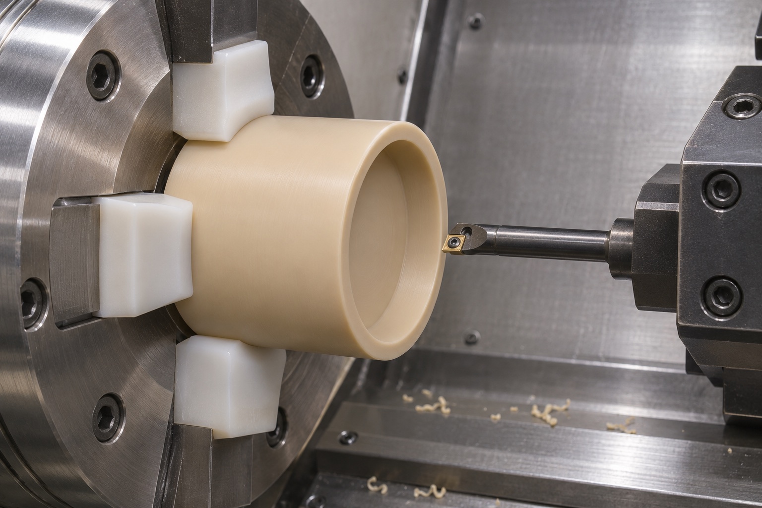
The recess changes the supported section of the cylinder, so plan gripping locations and the order of outside and inside operations together. Review contact length, jaw shape and the surfaces that must remain free of unacceptable marks. The fixture must resist cutting forces without creating an unapproved distortion. A dimension measured under heavy clamping may not represent the released cap required for acceptance. Use support appropriate to the actual geometry and inspection condition, keeping contacts clean. Do not assume that a successful setup for a solid metal cylinder can be copied unchanged for a hollowed polymer cap simply because both have a round outside surface.
Choose a blind-recess route with realistic tool access
Determine how the opening, sidewall and floor will be produced using tools suited to the actual depth, diameter and corner definition. A preliminary hole may support a later finishing operation, but it must not leave an unapproved conical floor or excessive depth. Review tool reach, rigidity and clearance at the mouth. The proposed route should account for chip removal without adding an undocumented vent or opening in the closed end. Actual cutting conditions depend on the selected stock, tools and machine. Do not present an illustrative turning setup as evidence that a particular tolerance or complete internal profile has already been achieved.
Keep chips and heat from becoming hidden process assumptions
A blind recess does not provide the same exit path as a through-hole. Plan a suitable chip-evacuation and cooling approach for the actual operation, and verify that the selected method leaves the internal geometry accessible for review. Do not invent universal withdrawal intervals, feed values or cooling times from a material name alone. Define the required transition from machining to acceptance measurement, including environment and any specified stabilization condition. If an intermediate treatment is proposed, obtain approval and document its purpose. The goal is an interpretable manufacturing route, not a claim that an unspecified cooling period guarantees dimensional stability in every later shipping or storage condition.
Finish the mouth and internal transition without redesigning them
Identify the permitted mouth edge treatment and floor-to-wall transition in the drawing. An oversized entry chamfer can change the usable internal length or contact boundary. A convenient boring tool may leave a radius that requires design review rather than silent acceptance. Remove unacceptable burrs and loose polymer fragments while preserving the approved dimensions. Inspect the accessible recess and agree how any limited-visibility region will be assessed. A smooth outside surface does not prove the internal floor is clear of retained debris. Likewise, a dummy that enters after manual polishing cannot establish that the cap still meets its original wall, depth and profile requirements.
Build inspection around the recess and the released part
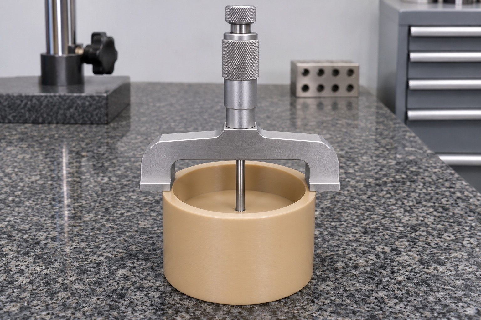
Map outside size, overall height, mouth, internal diameter, depth, floor condition and required geometric relationships to appropriate methods. A depth instrument spanning the rim can illustrate one possible measurement arrangement, but it does not prove the diameter, remaining section or complete floor geometry. Agree the contact and supporting references, measurement force and part state. Record actual first-article results rather than copied nominal values. Where requirements need a different view or method, state that scope explicitly. If the supplier cannot evaluate a feature credibly, disclose the limitation before an acceptance decision instead of implying complete verification from a photograph and a familiar instrument name.
Bound the supplementary dummy insertion observation
An approved inert probe-envelope reference can show gross access, visible contact and insertion behavior under a defined condition. Record its revision and the observation procedure. Do not use a real analytical probe, biological sample or operating instrument to improvise a trial. Successful hand placement cannot establish impact protection, retention, cleanliness preservation or compatibility with a real analyzer. If unexpected bottom contact appears, review both reference and cap dimensions before deepening the recess. The responsible design owner should decide whether the required envelope, component geometry or transport arrangement needs revision; ease of inserting one dummy is not permission to change a controlled part.
Specify internal cleaning and protective packaging distinctly
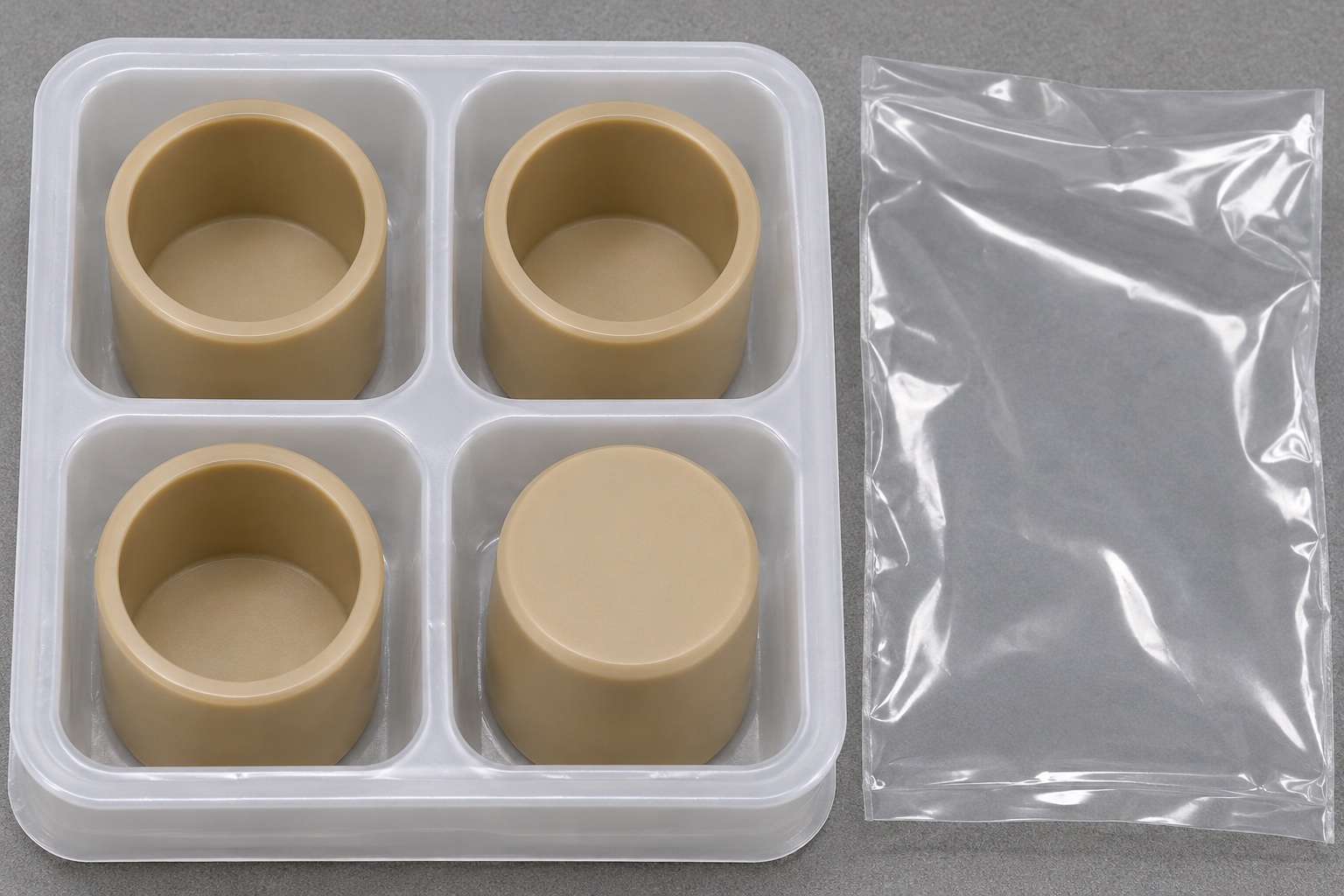
Agree cleaning agents, drying and outgoing handling condition for the actual grade and geometry. The closed recess needs a practical debris-removal and verification approach; ordinary rinsing is not evidence of a numerical residue limit or sterility. Protect the mouth and interior from loose packaging material, abrasion and pressure from adjacent parts. Separate caps where contact could change the agreed delivery condition. Link package identification to the part, revision and required records. A protective cap inside an ordinary bag is not a validated sterile-barrier system. Receiving inspection must follow the actual purchase requirements, not assume medical cleanliness from a natural polymer color or a tidy packaging scene.
Prepare a drawing-controlled RFQ for turned PEEK caps
Provide the released drawing, matching model, PEEK material definition, quantities and final condition. Highlight the inner envelope, depth reference, remaining-bottom requirement, mouth treatment and floor transition. Include the inspection state and required documentation, keeping any dummy observation separate from dimensional acceptance and transport validation. Ask the supplier to resolve tool reach, chip removal, gripping and measurement limitations during DFM. Preserve approved methods, actual first-article results and accepted changes for repeat manufacture. A complete RFQ makes custom medical analyzer protective fixture parts a measurable task without inventing customer deliveries, achieved capability, sterilization approval or proven protection for an actual analytical probe.
FAQ
Is this cap a through-bore sleeve?
No. It has one blind axial recess with an integral closed bottom. There are no vents, threads, inserts, flanges or through-holes in this geometry.
Does a depth measurement prove remaining bottom thickness?
Not by itself. Define both requirements and their references. Overall height, depth and floor condition must be evaluated with methods suitable for the specified remaining section.
Can a drain hole be added for easier chip removal?
Only after design approval. Adding an opening changes the deliberately closed cap and cannot be treated as an undocumented machining convenience.
Does the PEEK material name establish sterilization approval?
No. The actual grade, finished geometry, process and application require separately specified evidence. Material-family information cannot qualify a completed transport component.
Can one dummy insertion establish probe protection?
No. It is a bounded geometric observation. Impact, retention, real-probe compatibility and transport performance need separate requirements and validation.
What records help repeat manufacture?
Preserve drawing and material identity, approved clamping and recess-finishing methods, inspection state and references, actual measurements, accepted changes and packaging requirements.

tanghangyun@oemach.com