
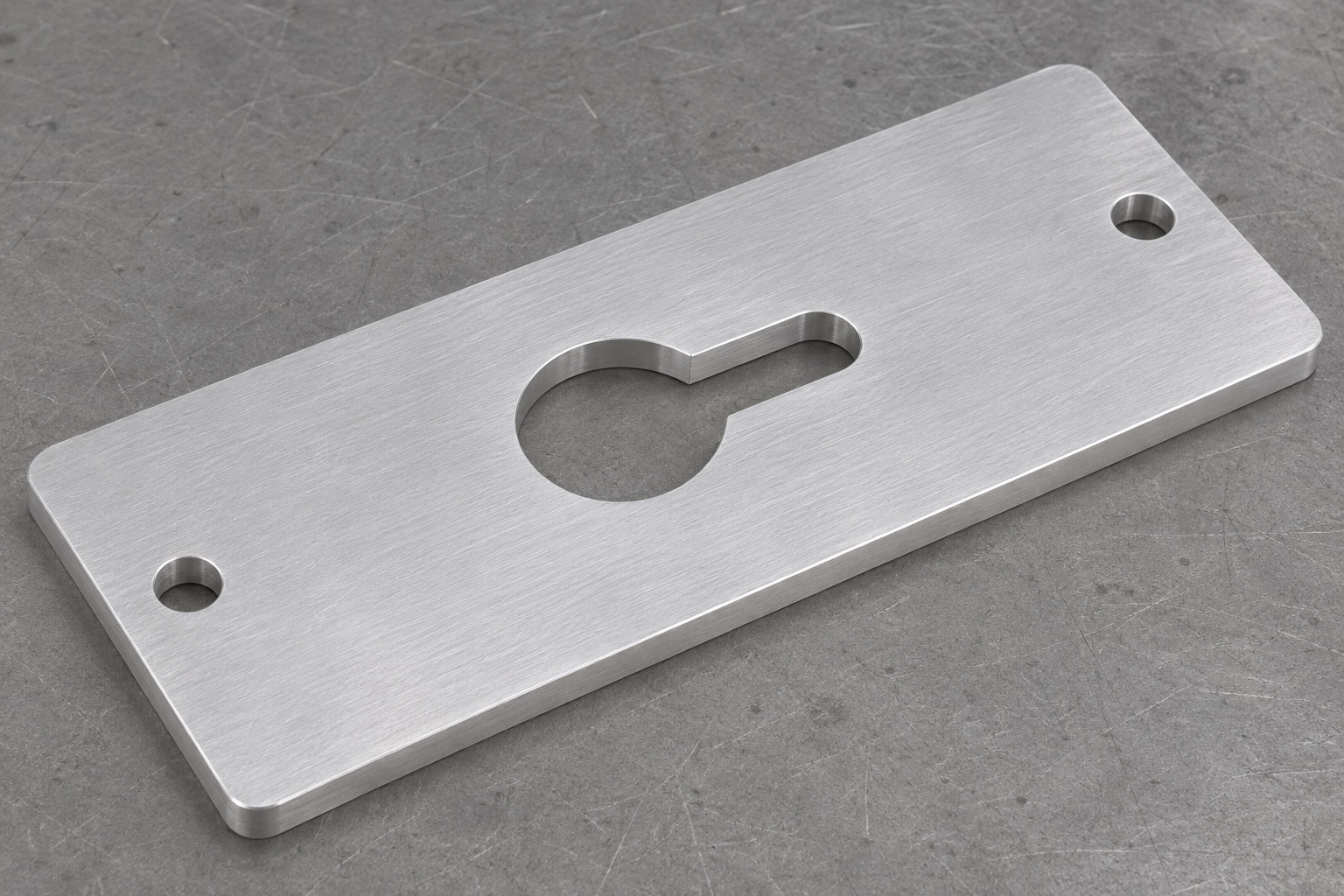
Describe the complete keyhole opening in the drawing
A service-fixture pass-through plate can have a larger insertion opening joined to a narrower positioning slot. The representative part here is a flat rectangular 6061 plate with two plain mounting through-holes near opposite ends and one enclosed keyhole-shaped opening in the middle. The circular portion connects to a short straight slot with a rounded terminal end, oriented along the plate's length. The opening does not reach an outside edge. This guide concerns an inert monitor service fixture, not a live cable protection system. Precision CNC milling begins by defining the separate circular and slot interfaces rather than calling the whole feature a convenient cutout.

Separate insertion clearance from the narrower slot function
Identify which part of the approved dummy connector passes through the larger opening and which envelope moves into the narrower section. Circle size, slot width and the connecting transition answer different assembly questions. A dummy that enters the circle may still encounter an unintended restriction during lateral movement. Conversely, a generous circle should not conceal an incorrect slot boundary. Define the required clear envelope and any functional contact surfaces on the drawing. Do not describe a keyhole profile as automatic cable retention, strain relief or electrical protection. Those functions require their own design requirements and evidence beyond the geometry of a machined plate.
Relate both openings and mounting holes to stable references
Choose the plate face and in-plane references required by the actual fixture. Specify the location and direction of the keyhole relative to those references, and define the two mounting holes separately. Avoid dimensioning each feature from a different convenient outside edge without considering how the plate is installed. The plate outline may provide handling clearance without being the functional locating boundary. A drawing should make that distinction visible so machining and inspection use compatible alignments. If the mating base or fastener arrangement establishes the installed position, include its approved definition in the design review rather than relying on the appearance of symmetry in the model.
Specify alloy condition and final surface requirements
Identify 6061, required supply condition, stock form and material records in the RFQ. Resolve coating, masking and final inspection stage before the surface is finished. A treatment can affect the opening or mating faces, so it should not be added as an informal aesthetic choice after dimensions have been accepted. The alloy designation and a satin surface do not independently establish cleaning compatibility, corrosion performance or electrical isolation. If those matters are relevant to a real service assembly, define the actual requirements and corresponding evidence. The manufacturing plan should state which surface condition is delivered without converting a material name into a system-level performance claim.
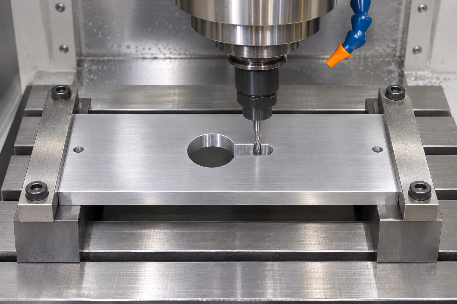
Review cutter access to the narrow section during DFM
The narrow slot, terminal radius and transition into the larger circle constrain tool access. Review the proposed cutter against the required profile and the full plate thickness. A large tool may reach the circular opening but not produce the narrow section or its specified transition. Resolve any minimum-radius or access limitation before programming. Do not widen the slot, move its end or break the opening through to the outside edge merely to simplify machining. A useful DFM conversation distinguishes functional contour changes from optional cosmetic details and records any agreed revision in the drawing and model before a supplier begins production.
Support the plate without hiding its free-state condition
Select workholding that keeps the cutter path accessible and supports the remaining sections as the opening is created. Review clamp locations relative to the mounting holes and the material around the keyhole. Keep backing clearance for breakthrough and avoid leaving a support condition that traps chips against a completed face. If the drawing controls flatness or another free-state requirement, define how that condition is checked after clamps are removed. A flat reading while the plate is forced against a fixture does not establish the same condition in service. The selected setup must be verified on the real part instead of being treated as a universal guarantee.
Rough and finish the connected contour as a controlled profile
Plan the sequence for the circle, straight neck and rounded terminal region with a recoverable reference. Review how tool entry, remaining allowance and finishing passes preserve the approved transition. The fact that the opening consists of connected simple shapes does not make their junction irrelevant. An unintended cusp or excess edge break can change clearance or contact. Use actual machining conditions suitable for the stock, machine and tool. A technical guide can explain the decisions, but it cannot claim achieved profile accuracy or production capability without manufactured components and a measurement method capable of evaluating the specified contour over its required extent.
Inspect both faces of the through-opening after deburring
The upper outline and lower exit can have different remaining edge conditions. Inspect accessible circle, slot and junction edges on both sides after loose debris is removed. Define the allowed treatment rather than applying an uncontrolled rounding operation until a dummy cable seems comfortable. The straight section must remain the required width, and the transition must retain its approved geometry. Include mounting-hole entrances and exits in the same review without confusing their acceptance with the keyhole contour. An edge that feels smooth on one face cannot establish the condition underneath, especially where the machining support or a later assembly would conceal the exit.
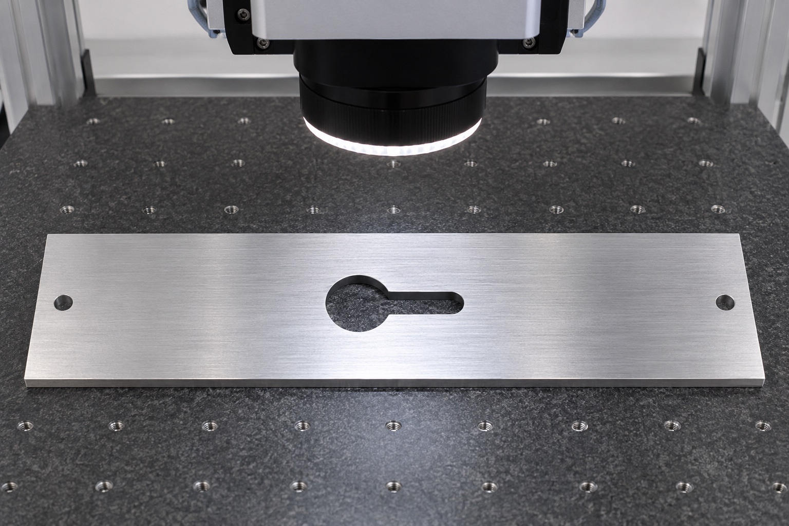
Match optical inspection to the actual acceptance question
An optical system may help evaluate the accessible outline, provided the method, alignment and relevant edge definition are agreed. The circular size, slot width, transition, terminal profile and feature position should each be addressed as required by the drawing. A top-view silhouette alone does not automatically establish sidewall condition or the exit edge. Where other methods are necessary, identify them rather than overstating the scope of an attractive inspection image. Record actual first-article results and measurement conditions. CAD contours, a photograph and the names of available instruments are not substitutes for evidence that the manufactured opening meets its complete requirements.
Keep a dummy movement check supplementary and unpowered
Use an approved inert connector envelope and fixture base if a supplementary insertion-and-slide observation is requested. Record the references and the direction of movement so the result can be interpreted consistently. Do not connect a live patient monitor or pull a working cable to invent a retention test. A dummy movement observation does not establish electrical safety, cable life, abrasion resistance or device compatibility. If a restriction appears, compare the actual dimensions, alignment and edge condition before widening the slot. Any change should be reviewed against the controlled drawing rather than accepted merely because one dummy arrangement becomes easier to assemble.
Define cleaning and packaging around the opening and faces
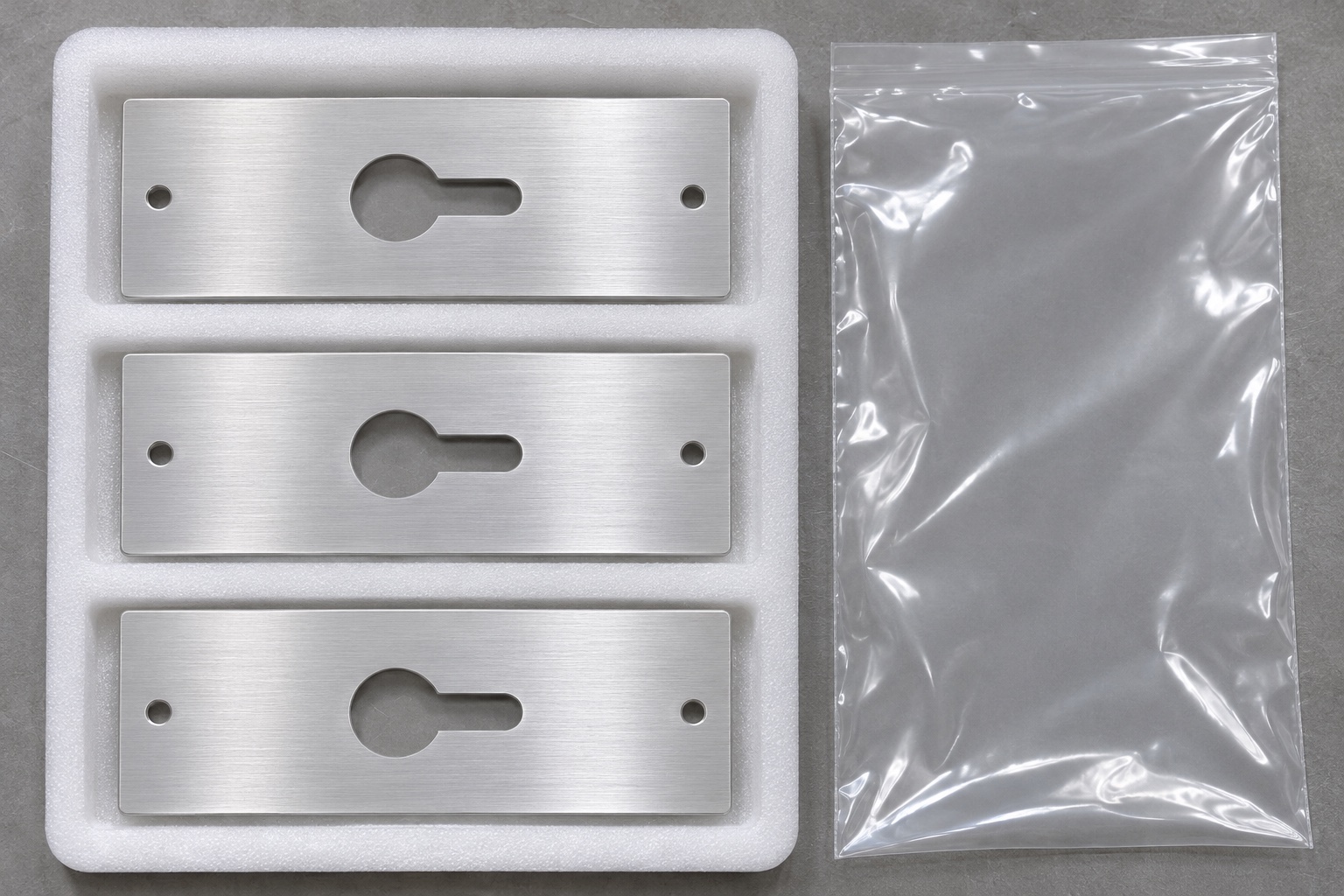
Agree permitted cleaning agents, drying and outgoing inspection condition before release. Remove loose chips from the keyhole neck and both mounting holes. Protect finished faces and narrow-section edges from rubbing and impact during handling. Packaging should separate plates without placing loose material inside the opening or forcing a distorted part against a rigid insert. Link package identification to the part number, drawing revision and required records. Ordinary manufacturing protection does not demonstrate a sterile barrier or validated residue removal. Receiving inspection should follow the actual purchase specification rather than accepting an intact clear bag and a visually clean metal surface as complete evidence.
Prepare a precise RFQ for low-volume keyhole plates
Provide the released drawing, matching model, 6061 requirements, quantity, final finish and documentation. Highlight the functional references, circle and slot definition, transition radii, mounting holes and required inspection state. Separate the supplementary dummy observation from dimensional acceptance. Ask the supplier to identify tooling, support and measurement limitations during quotation, with exceptions approved before manufacture. For repeat CNC orders, retain the approved setups and actual first-article results so changed conditions are visible. This creates a defined request for custom medical equipment aluminum parts without relying on a generic machining tolerance, a claimed customer success or an unsupported promise about cable protection in an operational device.
FAQ
Is the keyhole opening connected to an outside edge?
No. It is enclosed within the plate: a larger circular opening joins a narrower straight slot with a rounded terminal end along the plate length.
Does the plate automatically provide cable strain relief?
No. The geometry defines an inert pass-through interface only. Retention, electrical safety, bend limits and cable life need separate requirements and evidence.
Can the circular opening alone establish the keyhole fit?
No. Slot width, transition, terminal profile, position and relevant edges may all affect the approved dummy movement and require their own inspection.
Can a cutter limitation justify a wider slot?
Not without approval. Resolve tool access and allowed radii during DFM, updating the controlled drawing and model before changing a functional contour.
Does an optical outline prove every sidewall and exit condition?
No. Define what the method evaluates. Additional views or methods may be needed for sidewalls, lower edges and requirements not established by the visible outline.
What supports a consistent repeat order?
Retain material and revision identity, approved workholding, contour and deburring definitions, inspection alignment, actual results and packaging requirements, including accepted changes.

tanghangyun@oemach.com