
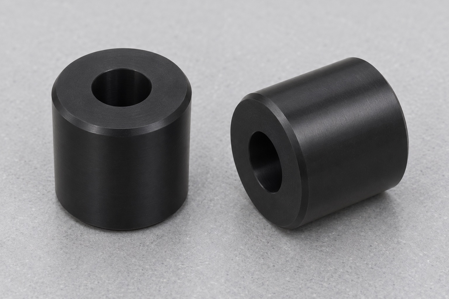
Define the roller and its limited transfer task
A cartridge transfer roller introduces three separate interfaces: the outer cylinder facing the dummy cartridge, the bore facing the axle reference and the ends facing neighboring supports. The representative POM-C part is a short black cylindrical roller with one plain axial through-bore and small edge breaks. It has no flanges, grooves, bearing inserts or hidden fastening features. This guide concerns an inert diagnostic-cartridge transfer fixture, not a validated analyzer transport mechanism. Precision plastic CNC turning should establish the required relationships between those interfaces before the supplier chooses how to hold the stock. The word roller alone does not define an acceptable fit, friction level or service life.

Separate the outside diameter from the axle fit
Identify whether the outer cylinder is a transport contact, a support surface or simply a clearance envelope. Its diameter and form should follow that role. Separately define the bore and its intended relationship to the axle: free movement, location and retention are not interchangeable requirements. A bore that accepts one pin may still fail a size or form requirement, while a smooth-looking outside surface does not establish the specified cylinder geometry. Avoid combining all these questions into a generic instruction for a close fit. The drawing and assembly definition must explain the functional interfaces without relying on a supplier to infer them from a familiar roller shape.
Specify roller length and the required end condition
The overall length affects clearance between fixture supports, but end-face condition can also influence seating and contact. Identify any required relationship between the ends, bore axis and outside cylinder. Where the assembly needs axial freedom, define the approved clearance and the condition under which it is assessed. Do not treat rubbing against a support as a problem that can always be solved by shortening the roller. Such a change may alter the intended cartridge support width or retention arrangement. Distinguish handling chamfers from functional end features so deburring does not create an unintended narrow support or interfere with the required measuring contact during inspection.
Keep POM-C grade and stock condition explicit
Specify acetal copolymer rather than using acetal, POM and other trade names as automatic substitutes. State the required color, grade, stock form and material records. Additives and supply conditions should be reviewed for the actual design instead of assuming all black plastic rods behave identically. Material identification belongs with the cut blanks and the traveler throughout turning and inspection. If the application has chemical, cleanliness or regulatory requirements, list the evidence that must be supplied for the particular material and use. A generic POM-C designation does not by itself establish those conditions, nor does it qualify the roller as a diagnostic instrument component ready for operation.
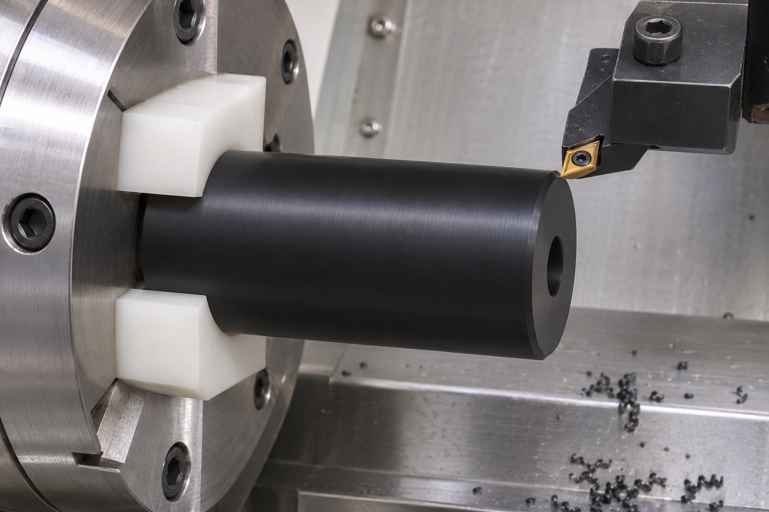
Choose plastic workholding that preserves the bore relationship
Review gripping length, jaw contact and the condition of the stock before defining the turning route. The fixture must resist cutting forces without imposing an unacceptable distortion on the part. A bore measured while the roller is tightly clamped can differ from its released condition, so the process and inspection plans must identify the relevant part state. Soft or shaped support may help, but its suitability depends on the geometry and requirements. Keep support contacts clean and avoid unapproved marks on functional surfaces. Do not assume a metal-part clamping approach can be transferred unchanged simply because the roller is short and the visible geometry is simple.
Plan outside turning and hole finishing together
Decide which operation establishes the references for the outer cylinder and axial bore. A common setup may help control their relationship, but the actual route must account for tooling access, chip removal and the final workholding reversal. Define how the second end is finished without sacrificing the approved references. Review whether the proposed hole-making and finishing tools can evaluate and produce the required bore condition over its full length. A through-hole is not automatically uniform merely because a tool reaches the far side. Avoid universal cutting parameters in the RFQ; require the supplier to select and verify a process appropriate to the specific POM-C stock and drawing.
Manage cutting heat and allow a defined inspection condition
Plastic parts need a controlled transition from machining to acceptance measurement. Agree the inspection environment and any required stabilization or conditioning period instead of measuring an arbitrarily warm component immediately after cutting. The correct condition depends on the application and specification; do not invent a universal waiting time or temperature. Review chip evacuation and tool condition as part of process planning. If a supplier proposes an intermediate treatment or an alternative stock preparation, obtain approval before applying it. The purpose is to keep machining and measurement conditions interpretable, not to claim that an unspecified cooling period guarantees dimensional stability in every future operating environment.
Remove bore-entry damage without changing the useful surface
Inspect both ends of the bore and the outside rim after turning and parting. Remove unacceptable burrs, loose slivers and retained chips without enlarging the bore or reducing the specified cylinder length. Small entry chamfers should remain within the drawing requirements. Do not use aggressive manual finishing to make a dummy axle fit when the actual issue is an incorrect bore size or reference alignment. Inspect the complete accessible bore and agree how any area with limited visibility will be evaluated. A finger check on the outside cannot establish internal edge condition, and a freely moving pin cannot demonstrate that no loose plastic debris remains inside.
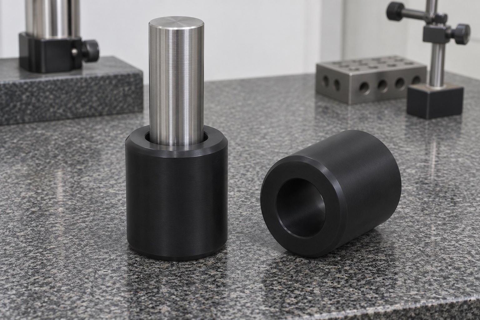
Build inspection around released dimensions and relationships
The first-article plan should cover outside size, bore size, length, edge condition and the specified relationships between surfaces. Choose contact force, support and measurement methods suitable for the plastic component and tolerance. Measure at the locations needed to evaluate the requirement rather than recording one convenient reading for the whole cylinder. Document part state and reference alignment. A rotating indicator check may reveal a relationship under a defined setup, but the mounting and reference can influence the observation. Do not report it as a universal runout result without defining what was measured. Actual readings and the method together support an acceptance decision; an instrument name alone does not.
Bound a supplementary dummy cartridge movement check
An approved inert axle and dummy cartridge can reveal gross rubbing, obstruction or inadequate access in the proposed fixture. Identify both references and describe the observation conditions. Do not extrapolate from a hand-moved dummy to an operating analyzer's reliability, transport accuracy or cartridge protection. The roller may require a separate retention design that is outside the simple geometry shown here. If movement is inconsistent, compare actual dimensions and alignment before changing the bore, shortening the part or adding lubricant. Any lubrication or surface modification must be approved for the application. A supplementary movement observation cannot replace the dimensional report or the system owner's qualification of a real transfer mechanism.
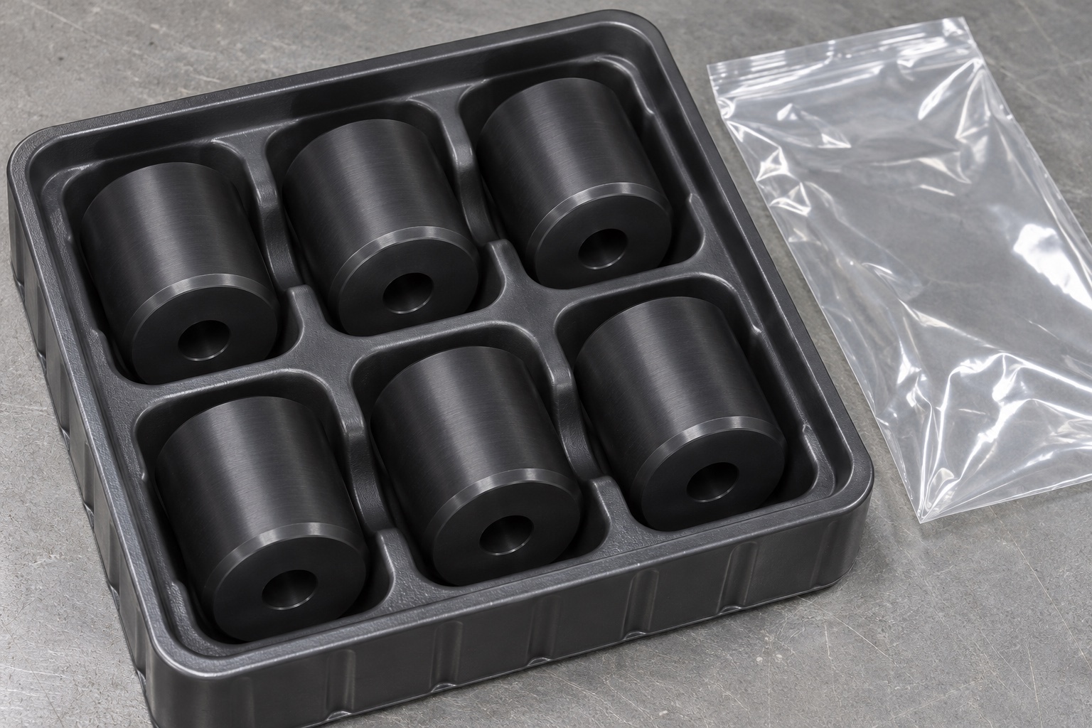
Define cleaning and protective handling for acetal rollers
Agree cleaning agents, drying and incoming cleanliness expectations before shipment. Remove chips from the axial bore and protect the outside contact surface from abrasion or contamination. Keep finished rollers separated where rubbing or mixed-part handling could compromise their condition. Packaging inserts should not shed unacceptable material or preload the roller in a distorted state. Identify each package with part and revision information linked to the required manufacturing records. Ordinary protective packaging does not establish a sterile barrier or validated chemical compatibility. If cleanliness limits are important, define the assessment and records explicitly rather than accepting a visually clean black surface as sufficient proof of compliance.
Prepare a drawing-based request for low-volume turned parts
Supply a released drawing, matching model, POM-C material definition, quantity and required final condition. Highlight the outer contact cylinder, bore function, length and end-clearance requirements, inspection state and documentation. Ask for DFM review of workholding, bore access, finishing and measurement limitations. Keep requested dummy movement checks separate from dimensional acceptance and operational validation. For repeat batches, retain the actual first-article results, approved setups and any accepted changes instead of copying nominal values from the original model into a new report. This creates a useful basis for custom medical analyzer fixture components without inventing a customer delivery, achieved capability, operating performance or regulatory approval.
FAQ
Does the representative roller contain bearings?
No. It is a plain POM-C cylinder with an axial through-bore. Bearings, grooves, flanges and retention hardware are not part of this geometry.
Can POM-H replace POM-C automatically?
No. Specify and control the required material. Any substitution, including a different acetal family, grade, color or additive package, needs approval against the actual requirements.
Does a passing dummy axle prove bore conformity?
No. It is a supplementary observation. Bore dimensions, form and relationships need suitable inspection against the drawing, with the part in its specified condition.
Why record the condition before measuring a plastic roller?
Machining, support and measurement conditions can affect interpretation. Define the required environment and part state so results can be compared and assessed meaningfully.
Does smooth hand movement prove analyzer performance?
No. An inert fixture check cannot establish transport reliability, cartridge protection, service life or diagnostic performance. The actual mechanism requires separate qualification and evidence.
What information belongs in the roller RFQ?
Include drawing and model revisions, POM-C definition, quantities, bore role, cylinder and end requirements, inspection conditions, cleaning, packaging and the required manufacturing documentation.

tanghangyun@oemach.com