
Start with the inspection contact rather than the round outline
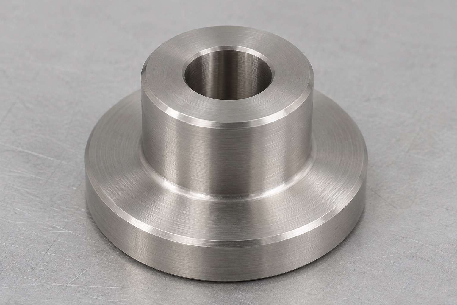
A datum button gives an inspection fixture a defined mechanical contact. For a surgical instrument manufacturing fixture, the useful questions are where the inspected item rests, which surfaces locate the button, and how the mounting arrangement affects that contact. The representative geometry here is a wide circular flange with a smaller cylindrical boss, a flat top and one plain axial through-bore. It has no thread or counterbore. This guide addresses custom fixture manufacture, not an implant or a validated instrument inspection system. Precision 316L CNC turning can produce the intended surfaces only after their functions and acceptance requirements are made explicit in the released drawing.

Identify the mounting face and contact height
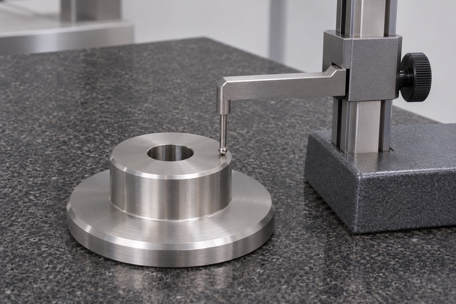
Distinguish the underside of the flange, the upper boss face and the annular shoulder between them. The mounting face provides the installed reference; the boss face provides the proposed contact. Specify whether contact height is measured from the flange underside and whether flange thickness has its own functional requirement. These dimensions answer different questions. If several buttons establish a support plane, define the required assembled relationship rather than assuming equal catalog dimensions create the intended plane. A height measured on a surface plate can support inspection, but it cannot identify an undefined drawing datum or prove that the complete fixture locates a surgical instrument correctly.
Decide what the through-bore actually locates
The axial bore may provide fastener clearance or a locating interface, depending on the approved design. State which role applies. A clearance hole should not silently become the primary centering feature during inspection, and a locating bore needs more definition than an instruction to drill through. Specify the relevant size, form and relationship to the contact surfaces. Review the approved fastener or pin envelope without adding a recess that the model does not contain. Where the bore entrance has an edge break, distinguish it from a functional chamfer or a screw seat. The plain hole shown here does not accommodate a hidden threaded connection.
Keep material identity connected to small turned blanks
Specify 316L stainless steel, stock condition and the material documentation needed for the order. Traceability is easily lost when several visually similar short blanks share a tray. Link the blank container or process traveler to the drawing revision and stock identity before machining. Do not infer grade from appearance or replace it with another stainless material because both can be turned. If a supplier proposes a material change, assess it before production. Material identity supports the manufacturing record, but the grade name alone does not establish contact suitability, cleaning resistance or the functional accuracy of an inspection fixture assembled from the finished buttons.
Plan the first turning setup around recoverable references
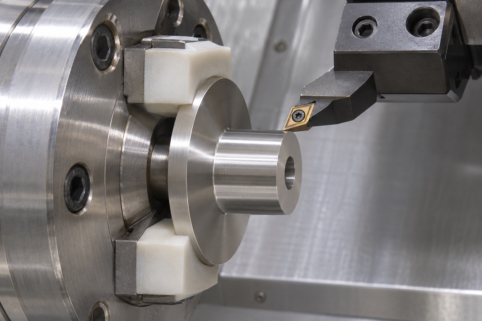
Review stock allowance, jaw engagement, tool reach and the intended order of facing, outside turning and bore production. A stable first setup should establish features that can be recovered during the reverse operation without damaging the contact face. Indicate which surfaces are roughing references and which become finished functional surfaces. Machining drawings should not leave the operator to select a convenient edge as the final datum. Actual feeds, speeds, insert geometry and coolant depend on the stock, machine and tooling. A purchasing article can explain the planning decisions, but it cannot supply a universal cutting recipe or claim an achieved tolerance without a manufactured part and real measurements.
Protect the boss and flange during reversal
The reverse setup must hold the part securely while preserving previously finished surfaces. Check whether the selected jaws contact the flange, boss or a temporary machining allowance. Keep chip-contaminated contacts out of the workholding interface. A small trapped chip can affect seating or leave a mark that later becomes a false inspection contact. Complete the underside and final length with a documented reference-recovery method. If a soft jaw or fixture insert is used, identify its approved geometry and condition. A visually polished boss does not demonstrate that the opposite face was produced at the required height or orientation after the component was released from the chuck.
Treat shoulder transitions as drawing-controlled geometry
The flange-to-boss transition needs enough definition to avoid an accidental interference with the mating fixture. Identify the permitted radius, relief or sharpness requirement where it matters. Do not add a tool-clearance groove simply because a standard insert would otherwise leave a transition. A mating component may sit on the flange shoulder, or it may deliberately clear it; those alternatives lead to different acceptance checks. Tool accessibility should be reviewed during DFM, before the supplier commits to the process. If the drawing cannot be produced with the available tooling, agree a revision rather than allowing an undocumented shop-floor geometry change to become the new design.
Finish edges without moving the intended contact
List the boss rim, flange rim and both bore entrances in the deburring plan. The goal is to remove unacceptable burrs while preserving the specified contact area and dimensions. A generous manual edge break can reduce a narrow contact face or change the usable mounting section. Use appropriate visual access and magnification where needed, and distinguish a loose chip from a remaining attached burr. Define how the condition is accepted instead of relying on the instruction that every part should feel smooth. Any polishing, passivation or other surface treatment must follow the actual order requirements and be considered when deciding when final dimensions are measured.
Build a first-article inspection sequence for datum buttons
Create an inspection matrix that maps each requirement to a method and reference alignment. Height, flange thickness, bore size, boss diameter, seating-face condition and specified geometric relationships require distinct evidence. Record the part state, supporting surfaces and measurement conditions. A coordinate measurement may help evaluate positional relationships, while other instruments may be more suitable for individual sizes; equipment selection must follow the actual tolerances and access. Do not present nominal CAD values as measured results. First-article inspection should establish whether the approved manufacturing and inspection methods can evaluate this drawing, not merely demonstrate that a component looks like the model in a photograph.
Separate fixture assembly observations from dimensional acceptance
A dummy mounting plate and approved fastener reference can reveal access restrictions, rocking or unintended contact. Record the reference revision and mounting condition so the observation can be repeated. This check is supplementary: tightening a screw may conceal a seating discrepancy, and successful assembly does not establish all drawing dimensions. Do not use a real instrument or a production acceptance decision as an improvised experiment. The design owner must qualify the complete inspection fixture and its method for the intended task. A custom turned button remains one component within that system, even when its own dimensional report shows conformity to the released manufacturing drawing.
Specify cleaning and packaging as controlled handover conditions
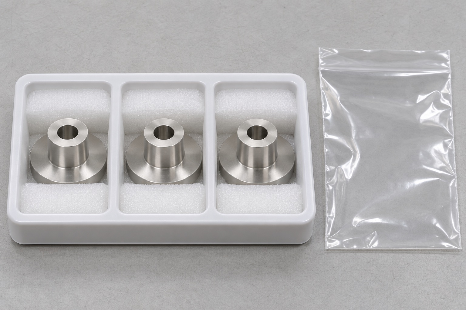
Agree cleaning, drying and outgoing inspection requirements with the purchase order. Remove loose machining debris from the axial hole and protect both end faces from handling damage. Separate individual buttons when contact between metal parts could damage the boss or seating surface. Packaging should preserve the agreed condition without depositing loose fibers or particles into the bore. Identify packages with the part number, drawing revision and records needed at receipt. Ordinary protective packaging is not sterile-barrier packaging, and routine cleaning does not establish a quantitative cleanliness limit. Such requirements must be separately specified, performed and supported by evidence before they appear as delivery claims.
Prepare an RFQ that supports repeat low-volume CNC orders
Supply a controlled drawing and matching model, material requirements, quantities, delivery condition and inspection expectations. Highlight the mounting face, boss contact height, bore function, transition requirements and any set-matching condition. Ask the supplier to identify unresolved tool-access or measurement issues during quotation. Separate the cost of first-article evaluation, special fixtures and supplementary dummy assembly checks from recurring part manufacture where practical. For repeat orders, retain the approved setup and inspection revisions alongside actual results. This makes precision stainless steel machining a defined purchasing task rather than a promise based on a generic tolerance statement, a photograph or the fact that the component is intended for a medical manufacturing environment.
FAQ
What makes a datum button different from a spacer?
Its defined contact and locating functions determine the inspection requirements. A similar outline does not establish the same contact height, seating reference or fixture role.
Does the central hole have a counterbore?
No. This example has a plain axial through-bore. Its entrance edge treatment must not be described as a cylindrical screw-head recess or an internal thread.
Can one height reading establish the complete button geometry?
No. Height is one requirement. Bore size, seating condition, boss diameter and specified geometric relationships need their own suitable evaluation methods and references.
Should every button in a fixture have matched height?
Only if the approved fixture requires it. Define the set requirement, reference condition and acceptance method rather than inferring it from nominally identical individual parts.
Does 316L establish inspection-system approval?
No. Material identity does not qualify the complete fixture, measurement method or inspected surgical instrument. Those responsibilities remain separate from manufacturing the button.
What records help with a repeat order?
Preserve the released drawing, model, material identity, approved workholding, inspection method, actual first-article results and packaging requirements, including any accepted changes.

tanghangyun@oemach.com