
Fuel cell test fixtures often include aluminum bases, copper contacts, insulators, positioning pins and sealing structures. The difficulty lies not in single-piece processing, but in whether each interface can work in the same assembly sequence. OEMach will separate the positioning, clamping, conductive and sealing functions before five-axis machining to clarify the reference transmission between each part.
The structure of fuel cell test fixtures is often not as simple as a standard fixture: it not only allows the tested parts to be placed repeatedly, but also leaves reasonable space for conductive parts, insulating parts and sealing areas. Once the size, contact position or pipeline direction of the part under test is adjusted during the R&D stage, the base, pressure plate, positioning pins and copper parts may change at the same time. If processing is only split into single parts, what is most easily missed is the dimension chain between multi-material interfaces.
Design inputs, machining controls and delivery impact
| functional area | Should be confirmed in advance | Easy to cause rework |
|---|---|---|
| Positioning pins and positioning holes | Pin diameter fit, pin height and main datum | Repeated placement of the tested part is unstable |
| Sealing surface and sealing groove | Seal type, contact area and surface requirements | Partial stress or unreliable sealing after pressing |
| Copper conductive interface | Contact surface protection, connection methods and disassembly and assembly directions | Poor contact or assembly interference |
| Insulation interface | Materials, wall thickness, thread scheme and insulation clearance | Deformation or interference between adjacent parts after tightening |
First distinguish the responsibilities of positioning, clamping, sealing and conduction
The positioning pin is responsible for repeated positioning, the bolt or pressure plate is responsible for clamping, the sealing surface is responsible for contact and sealing conditions, and the copper parts serve for conductive or signal connections. They are not substitutes for each other. During the processing review, it should be clarified who is the main positioning surface, which holes are clearance holes, whether surface treatment is allowed in the sealing area, and how to leave assembly and replacement space between copper parts, aluminum parts, and insulation parts.
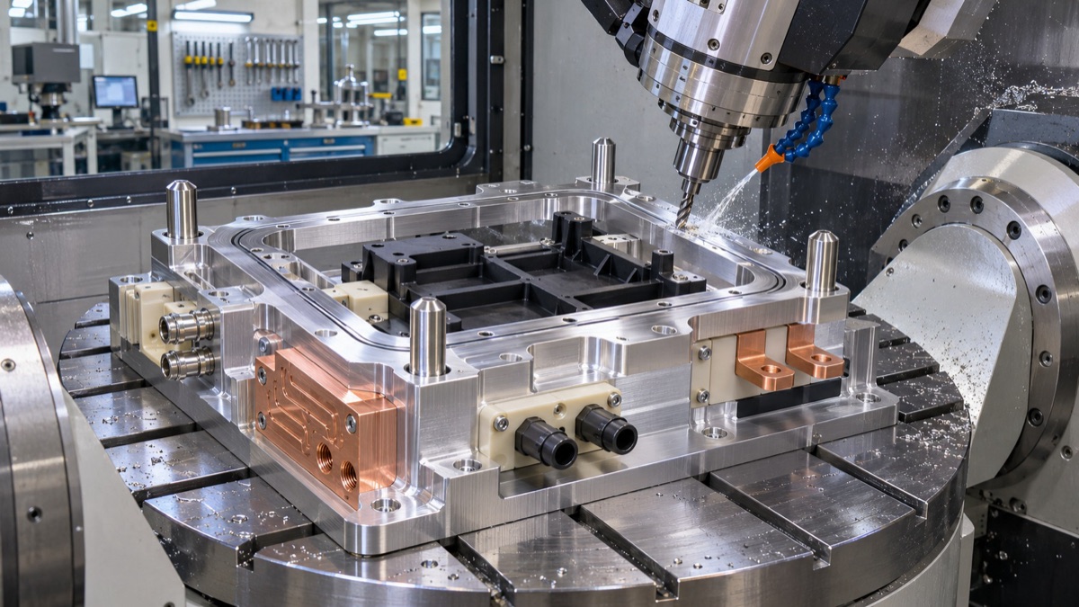
Figure 1: Aluminum base, copper parts and insulating interface in five-axis machined fuel cell test fixture.
Multi-angle interface is suitable for processing with the same coordinate system
When there are lateral interfaces, inclined mounting positions, sealing grooves and multiple sets of hole systems on the fixture, five-axis machining can help incorporate key features into unified coordinates and reduce errors caused by repeated clamping. But five-axis is not an automatic solution, and the premise is still that the datum, critical sealing areas and assembly sequence are clearly defined in the drawings. For removable modules, you should also confirm whether there is enough operating space for tools.
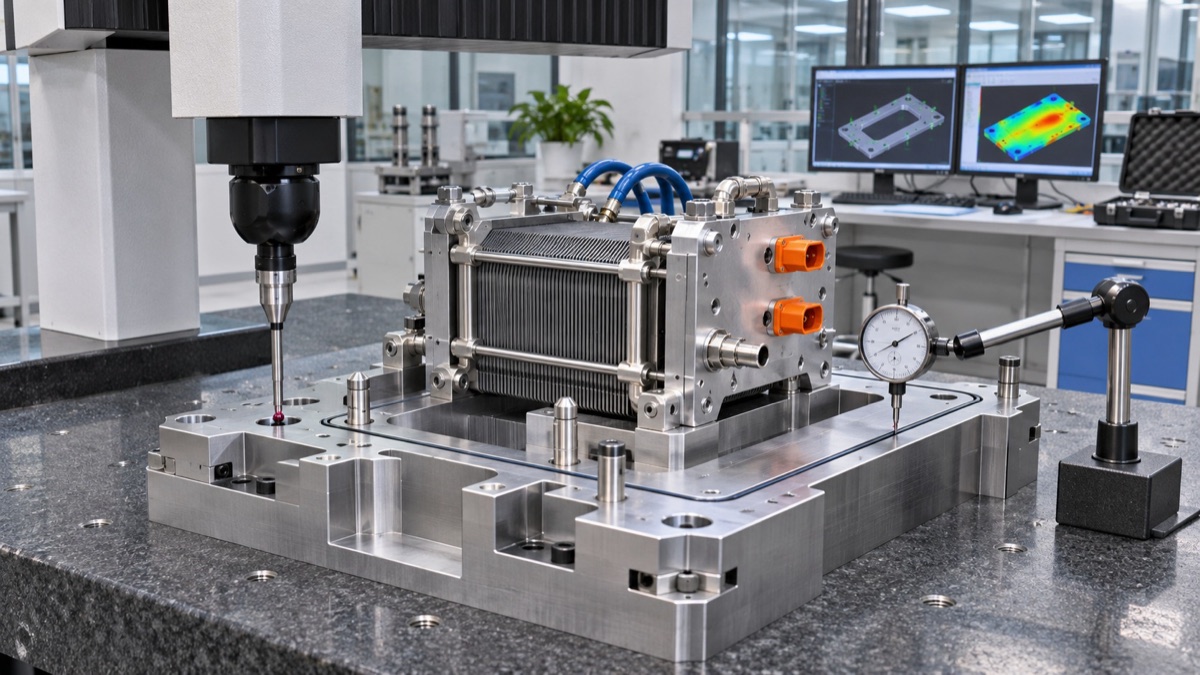
Figure 2: Confirm fixture positioning, sealing and interface characteristics through three-dimensional coordinates and measuring tools.
Mixed materials cannot be ordered piece by piece only based on BOM.
Aluminum alloys, copper alloys and engineering plastics have different processing and surface conditions. For copper parts, more attention must be paid to burrs and contact surface protection, for aluminum parts, reference and hole locations must be processed, and for insulating parts, material grade, inserts, and minimum wall thickness must be confirmed. If these parts are ultimately assembled on the same fixture, an assembly drawing is needed that reflects the interface relationship, rather than just their respective parts lists.
Include first article assembly as a condition of delivery
OEMach recommends that the first piece test assembly be used as a key verification in the small batch stage: check the placement of the tested part, insertion and extraction of positioning pins, pressure plate travel, copper parts contact and insulation parts avoidance. In this way, the actual use conditions of the test fixture can be pre-loaded into the processing acceptance, instead of waiting until the test bench for intensive rework.
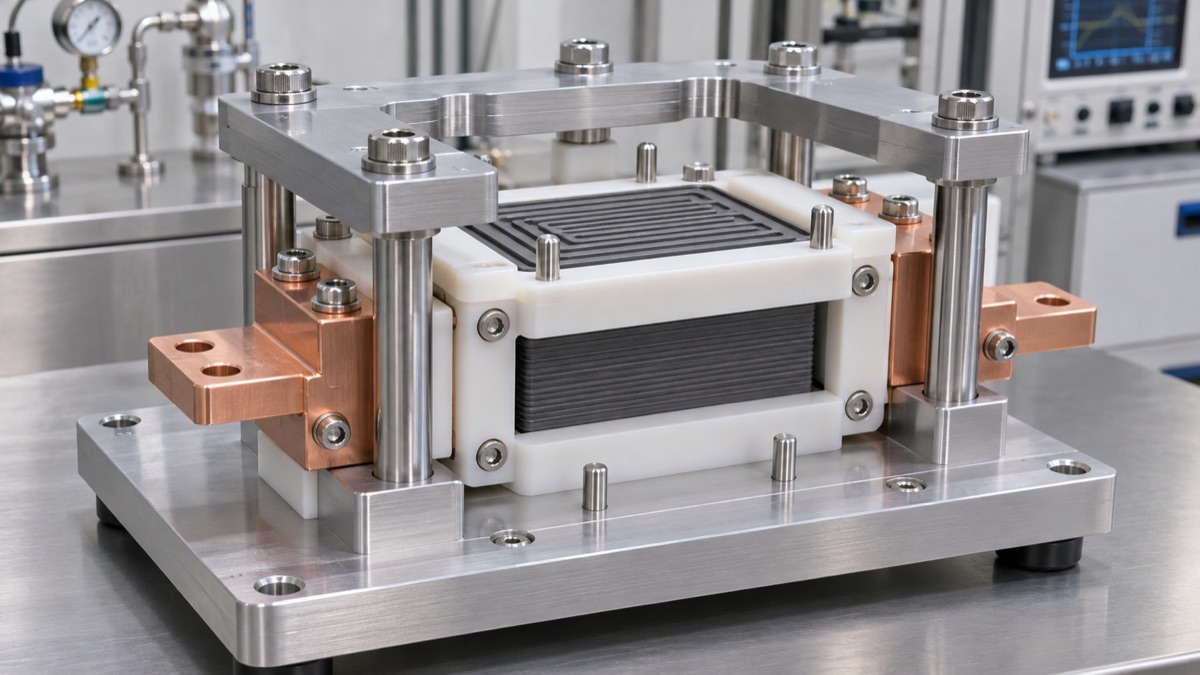
Figure 3: Schematic of the assembled fuel cell test fixture product.
Summary
If the project contains multi-material interfaces, please submit the BOM, exploded view, shape of the component under test, sealing plan and key assembly sequence together. The earlier the five-axis machining review is centered around the actual use status, the easier it will be for the first piece to go directly to verification.
FAQ
1. Why does the test fixture require five-axis machining?
Multi-angle mounting surfaces, lateral interfaces, complex cavities, or hole systems that need to maintain spatial relationships may be more suitable for five-axis machining. The actual judgment still needs to be based on the structure.
2. What surface treatment is required for the sealing surface?
It needs to be decided based on the seal type, contact medium and assembly method. The key is to first clarify the functional requirements and then select the corresponding process.
3. Can copper, aluminum and insulation parts be coordinated by the same processing plant?
Yes, but it should be confirmed that the supplier can handle different materials separately and manage the basis, protection and delivery according to the final assembly relationship.
4. How to distinguish locating pin holes and bolt holes?
The positioning pin holes are used for repeated positioning, and the bolt holes mainly provide clamping or adjustment. The size and assembly sequence of both should be clear in the drawings.
5. How to reduce subsequent modifications of small batch test fixtures?
Provide the appearance, interface, assembly sequence and module replacement requirements of the device under test as early as possible, and arrange the first piece trial assembly.
Ready to get a quote for your CNC machined parts?
Submit your engineering drawings to qiancj@oemach.com. We support prototype sampling and small-batch production with strict tolerance control.