
The servo reducer housing assembly is stuck, the bearing is pressed in abnormally, or the sealing surface is unstable. It is often not a problem of a single hole diameter, but the relationship between the hole axis, sealing surface and mounting hole is not consistent. In the review of non-standard parts processing, OEMach will first deduct key benchmarks from the assembly chain of bearings, output shafts and motor interfaces.
The reducer housing is not completed by boring out a few bearing holes. It has to bear the bearing outer ring, output shaft, end cover, motor flange and sealing structure. Any reference change may become resistance during assembly. Especially in the prototype or small batch stage, when the aperture, stop, sealing surface and mounting hole on the drawing are defined by different people, it is easy for a single piece to pass the test but the assembly does not go smoothly.
Design inputs, machining controls and delivery impact
| location | Processing and testing focus | Abnormal assembly performance |
|---|---|---|
| Bearing hole | Bore diameter, roundness and coaxial relationship with adjacent bores | The bearing is unevenly pressed or the rotation resistance is too large |
| End cover sealing surface | Flatness, surface condition and relative hole axis relationship | Risk of unstable end cap fit or seal failure |
| Motor installation stop | Stop diameter and end face position | The motor and reducer are not concentric |
| Mounting holes and positioning holes | Main positioning, clearance holes and tightening sequence | On-site assembly is stuck or the holes are difficult to align |
The bearing hole should be placed into the entire transmission chain to determine
The size of the bearing hole is only the first step. More attention needs to be paid to the coaxial relationship between the front and rear holes, the verticality of the hole axis relative to the sealing surface of the end cover, and the height of the bearing hole relative to the motor interface surface. If the outer contour of the shell is regarded as the only front surface, the hole system that is actually responsible for rotational positioning may produce cumulative deviations after multiple clampings. Processing and inspection should try to establish the same set of coordinates around the bearing hole, end face and positioning stop.
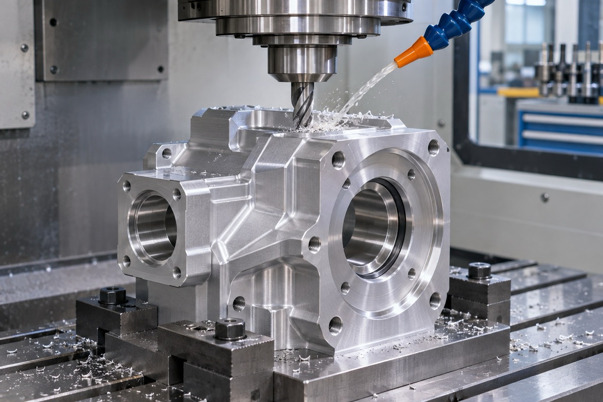
Figure 1: CNC machining of the bearing hole, stop and sealing surface of the servo reducer housing.
The sealing surface should not be regarded as an ordinary appearance surface
The role of the housing end face depends on the sealing type: it may be the end cover contact surface, the O-ring groove reference, or the bearing surface of the bearing gland. Flatness, surface condition, bolt hole distribution and local chamfers may all affect assembly. If the sealing surface is also the positioning reference for the bearing hole, the process route should avoid damaging its relationship during subsequent turning.
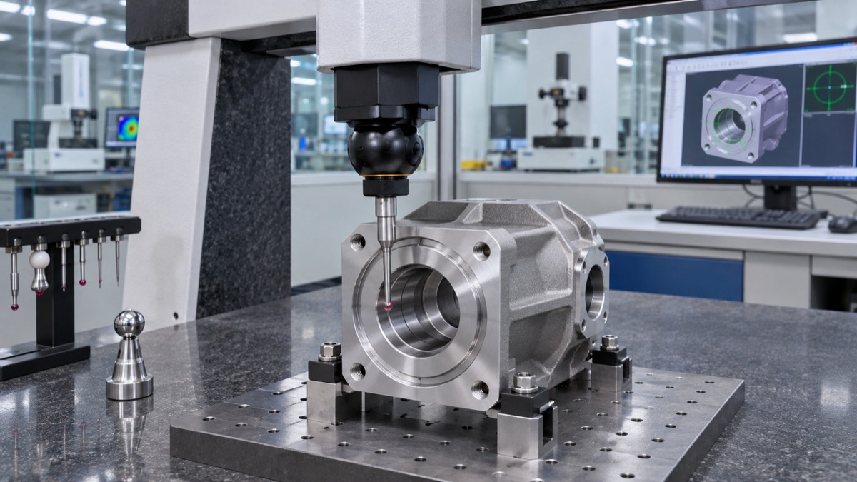
Figure 2: Three-dimensional coordinate inspection of the relationship between the axis of the reducer housing hole, the end face and the mounting hole.
The shell material and process must match the structure
Aluminum alloy shells facilitate weight reduction and processing, but thin-walled, deep-cavity or large-opening structures are more susceptible to clamping; steel parts or castings need to pay attention to the allowance, internal stress and datum state. There is no one fixed route that fits all housings. A more practical approach is to arrange roughing, stress relief, finishing and necessary hole system retesting based on material, wall thickness, bearing hole grade and batch size.
The first piece should be looked at together with the bearings and end caps
OEMach recommends that such housings be verified at the first article stage in conjunction with actual bearings, end caps or equivalent inspection fixtures. This allows problems such as press fit, end fit, and bolt accessibility to be discovered at the same time, avoiding the need to wait until all parts are assembled before locating the source of the error.
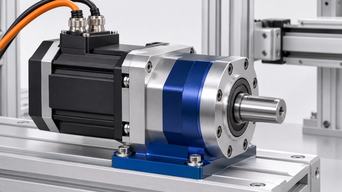
Figure 3: Schematic diagram of the completed reducer housing and servo motor assembly.
Summary
When inquiring about the reducer housing, please state the bearing model, end cover sealing form, motor seam and assembly direction. Only when the processing plan is aligned with the actual transmission chain can late-stage jamming and repeated repairs be truly reduced.
FAQ
1. Do the bearing holes have to be ground?
Not necessarily. Whether grinding is required depends on the material, hole diameter, tolerance, shape requirements and batch size; some structures can meet the requirements through processes such as precision boring.
2. Why does the assembly get stuck even though the hole diameter is qualified?
It may be related to the coaxiality of the front and rear holes, the verticality of the end face, the relationship between the seams, the actual tolerance of the bearing or the assembly method. You cannot just check a single hole diameter.
3. How to determine the roughness of sealing surface?
It should be determined based on the sealing form, sealing material and contact pressure. It is recommended that the design end clarify the functional requirements instead of just giving general surface treatment instructions.
4. Can small batch casings be used for first-piece trial assembly?
Yes. When bearings, end caps or interface inspection tools are provided, the true assembly status can be confirmed earlier.
5. What information is required for casing quotation?
It is recommended to provide 2D drawings, 3D models, materials, quantities, bearing/motor interface information, key hole systems and surface treatment requirements.
Ready to get a quote for your CNC machined parts?
Submit your engineering drawings to qiancj@oemach.com. We support prototype sampling and small-batch production with strict tolerance control.