
The needle racks, guide rail seats and positioning plates of laboratory automated pipetting workstations often come from different materials and processes, but they ultimately serve the same set of repeated positioning logic. When OEMach processes this type of small-batch parts, it will first look at the module movement direction, hole distance reference and sample plate interface, and then arrange processing and first-piece verification.
Parts drawings of pipetting workstations are often very detailed: the needle holder is on one drawing, the guide rail seat is on another drawing, and the sample plate positioning plate is on another drawing. When actually installing the machine, they must work together to ensure the relative positions of the suction head, sample plate and motion module. As long as the hole spacing, guide rail surfaces and positioning pins are from different coordinate systems, the equipment will easily experience plugging and unplugging irregularities, position deviations or the need for on-site gasket adjustment during the first run.
Design inputs, machining controls and delivery impact
| parts | Processing concerns | First suggestion check |
|---|---|---|
| Pipetting needle holder | Hole spacing, hole axis direction and clean chamfering | Insertion relationship to needle/tip assembly |
| Guide rail seat | Flatness, straightness and hole position of guide rail mounting surface | Fit and direction of movement to guide rail or slider |
| Sample plate positioning plate | Locating pin holes, stops and disassembly and assembly spaces | Positioning with actual plate type or simulated parts |
| Connection bracket | Assembly datum transfer and thread position | Does the tightening sequence affect the main positioning? |
First draw the repeated positioning chain
For this type of equipment, the most important question is not to ask which part is the most difficult to process, but to confirm where the action starts and where it is finally aimed. The needle holder hole spacing is usually related to the tip array; the guide rail base determines the direction of movement; the positioning plate and positioning pins constrain the position of the sample plate. If the final assembly profile, movement direction and key module interfaces can be provided before processing, the dimensional chain between parts can be identified earlier.
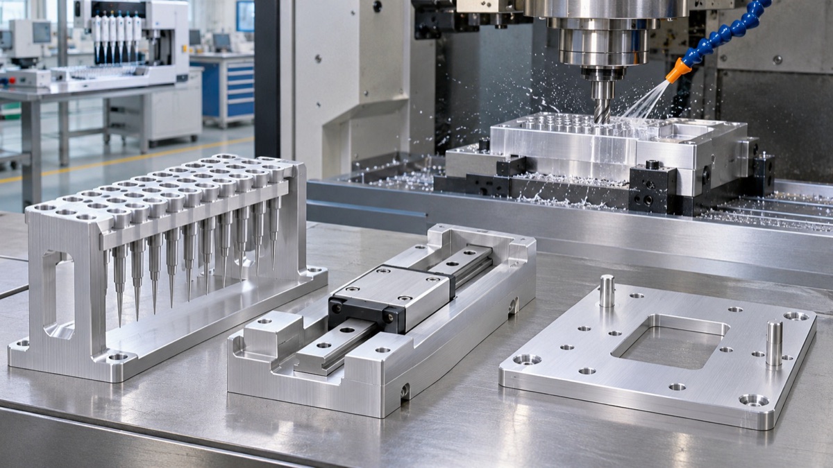
Figure 1: Processing of aluminum alloy parts such as the needle holder, guide rail seat and positioning plate of the pipetting workstation.
Hole spacing and guide rail surface need to be managed together
The hole spacing of the needle holder should not only look at the size between adjacent holes, but also the parallelism and height of the hole system relative to the guide rail mounting surface. For long guide rail seats, rough machining and then fine machining of the rail surface, positioning holes and mounting holes is usually more conducive to controlling deformation after loosening. If the positioning plate needs to be frequently replaced, the functions of the positioning pin holes and the bolt holes must be distinguished to prevent all holes from being handled in a tight matching relationship.
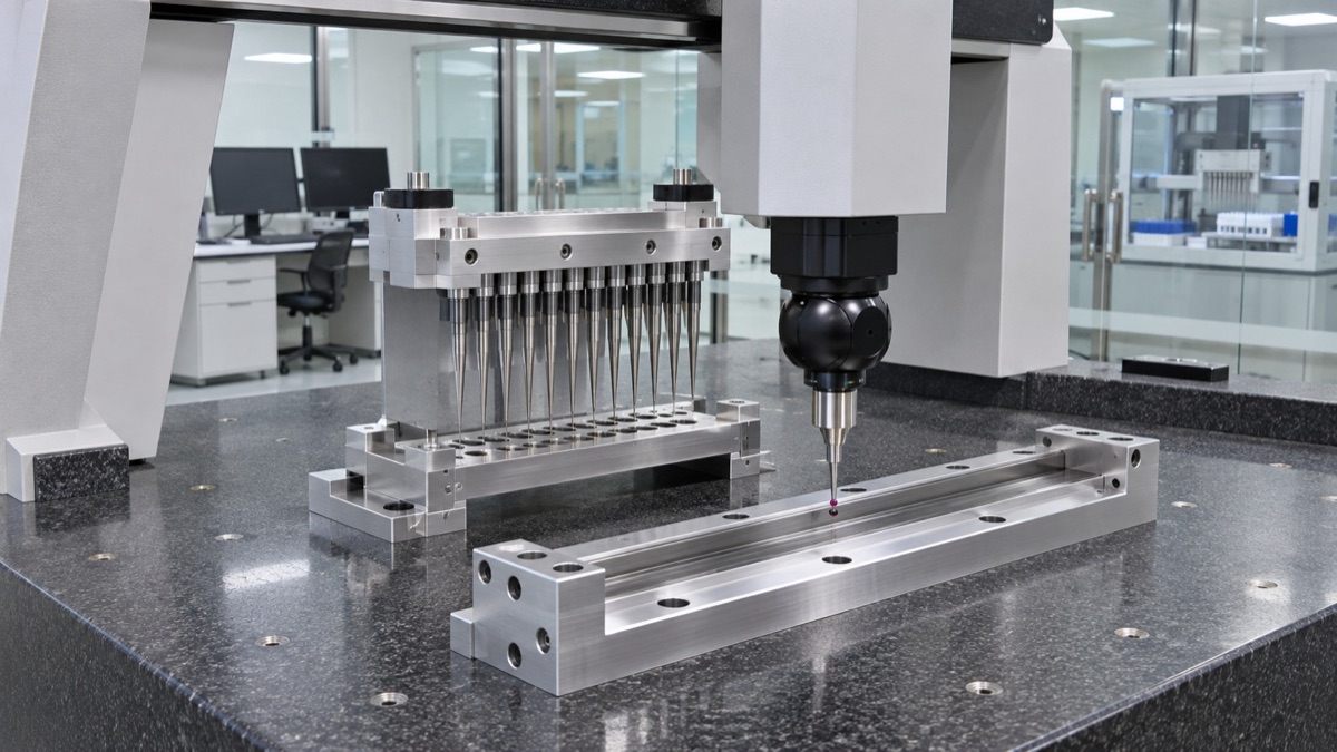
Figure 2: Three-coordinate inspection of the needle holder hole spacing, guide rail mounting surface and positioning features.
Small batch production does not mean putting parts into the same order
The core of matching is to let related parts reference the same set of master datums, and use the same set of inspection tools or the same first-piece trial assembly when necessary. If the customer only provides an isolated part drawing, the processing plant can still complete the single-piece manufacturing, but it will be difficult to determine whether there is a cumulative error between the needle holder hole array and the sample plate position. Therefore, assembly relationships are often more valuable than a single dimensional chart when equipment movement and multiple pieces fit together are involved.
The acceptance of the first piece depends on "whether it can operate smoothly"
OEMach recommends retaining at least one trial assembly of key interfaces during the R&D and prototyping stage: checking guide rail sliding, needle holder installation, positioning plate placement, and fastener accessibility. For laboratory automation equipment, dimensional reports are the basis, and the true assembly sequence and action space should also be included in the confirmation.
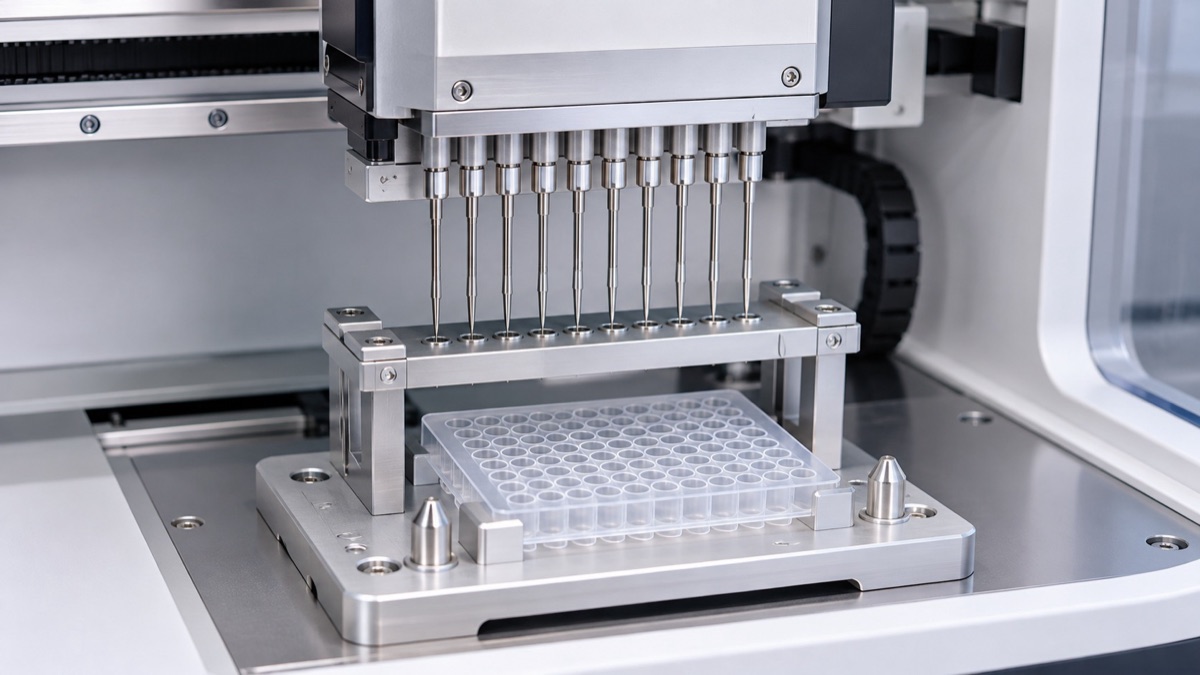
Figure 3: Assembly diagram of the needle holder and sample plate positioning components in the pipetting workstation.
Summary
When sending an inquiry, it is recommended to attach the sample board size, guide rail model or mounting hole spacing, movement direction and key assembly views in addition to the parts diagram. The earlier the module relationship is brought into the review, the more modifications can be reduced during the trial assembly phase.
FAQ
1. Does the hole spacing of the needle holder need to be very tight?
It needs to be judged based on the tip array, assembly method and detection capability. The relative position of functional holes usually deserves more priority control than ordinary mounting holes.
2. Why is the guide rail base easily deformed after processing?
Long thin-walled structures are greatly affected by clamping force, cutting heat and residual stress, and should be controlled through reasonable clamping, rough and fine separation and benchmark retesting.
3. Can the needle holder, guide rail base, and positioning plate be ordered in batches?
Yes, but the common datum and interface data should be retained. For complex projects, it is recommended to check according to the assembly relationship at the first article stage.
4. What materials are suitable for laboratory equipment parts?
It needs to be judged based on rigidity, corrosion resistance, cleaning method, weight and whether it comes into contact with reagents. Common aluminum alloys, stainless steel and engineering plastics have their own applicable scenarios.
5. How to avoid sample plate positioning rework in small batches?
Provide the actual plate shape or reliable interface size, and clarify the respective functions of the positioning pin, stopper, and clamping hole.
Ready to get a quote for your CNC machined parts?
Submit your engineering drawings to qiancj@oemach.com. We support prototype sampling and small-batch production with strict tolerance control.