
The industrial camera lens holder appears to be a flange with an inner hole, but the lens thread, sensor plane and equipment mounting surface often jointly determine imaging stability. Before OEMach processes such precision parts, it will first confirm the optical axis reference, lens interface and surface treatment range to avoid finding fit problems only during later assembly.
After an industrial camera is equipped with a lens, if the edges of the image appear uneven and the focus position is difficult to repeat, this is not necessarily a problem with the lens itself. If the relative relationship between the internal thread axis of the lens mount, the flange surface, and the sensor mounting surface comes from different processing standards, even if each individual dimension is within the tolerance, deviations may still accumulate to the imaging end after being installed in the camera.
Design inputs, machining controls and delivery impact
| key features | Relationships that should be confirmed | Common risks |
|---|---|---|
| Lens inner hole or thread | Coaxial and end-face relationship with sensor mounting surface | The optical axis shifts after the lens is locked |
| Flange mounting surface | Flatness and relative position to positioning holes | Change of focal plane direction after shell assembly |
| Mounting holes and locating pin holes | Which holes are responsible for positioning and which holes are responsible for clamping | Duplication of hole system constraints makes assembly difficult |
| black surface treatment area | Treatment requirements for mating surfaces, threads and masking surfaces | The film layer affects the fit or causes inconsistent appearance. |
First determine the real optical master benchmark
Some structures use the lens thread or inner hole axis as the main control object, while others use the sensor mounting plane and positioning hole as the benchmark. Both solutions can be done, but the coordinates cannot be changed separately in the drawing, processing and inspection links. Before quoting, you should clarify the lens interface model, whether there are gaskets or pressure rings, the installation direction of the sensor and lens mount, and which surfaces are actually functional surfaces involved in positioning.
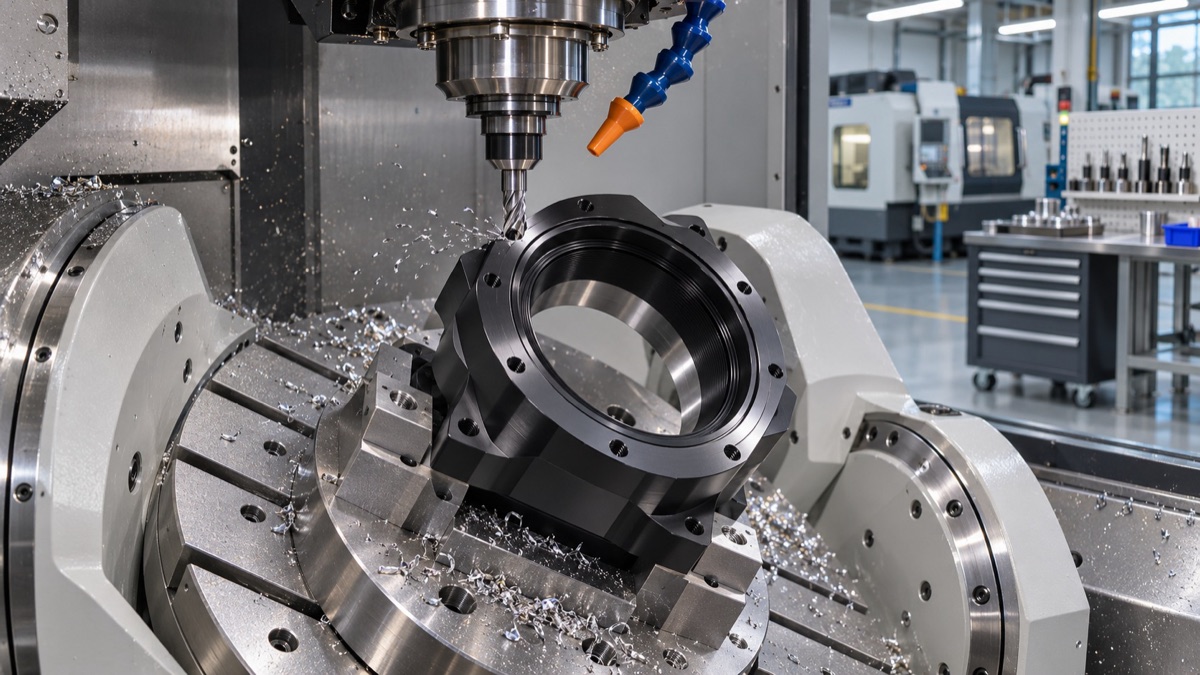
Figure 1: Five-axis processing of the flange surface and optical inner hole of the industrial camera lens holder.
The flange surface does not only need to be flat
The flange surface may be connected to the camera housing, or it may directly determine the position of the lens mount relative to the sensor. During processing, it should be placed in the same size chain as the optical inner hole and positioning hole. For multi-faceted structures or lateral interfaces, five-axis machining can reduce the datum conversion caused by re-clamping; but whether to use five-axis still depends on the part characteristics and key relationships, not the name itself.
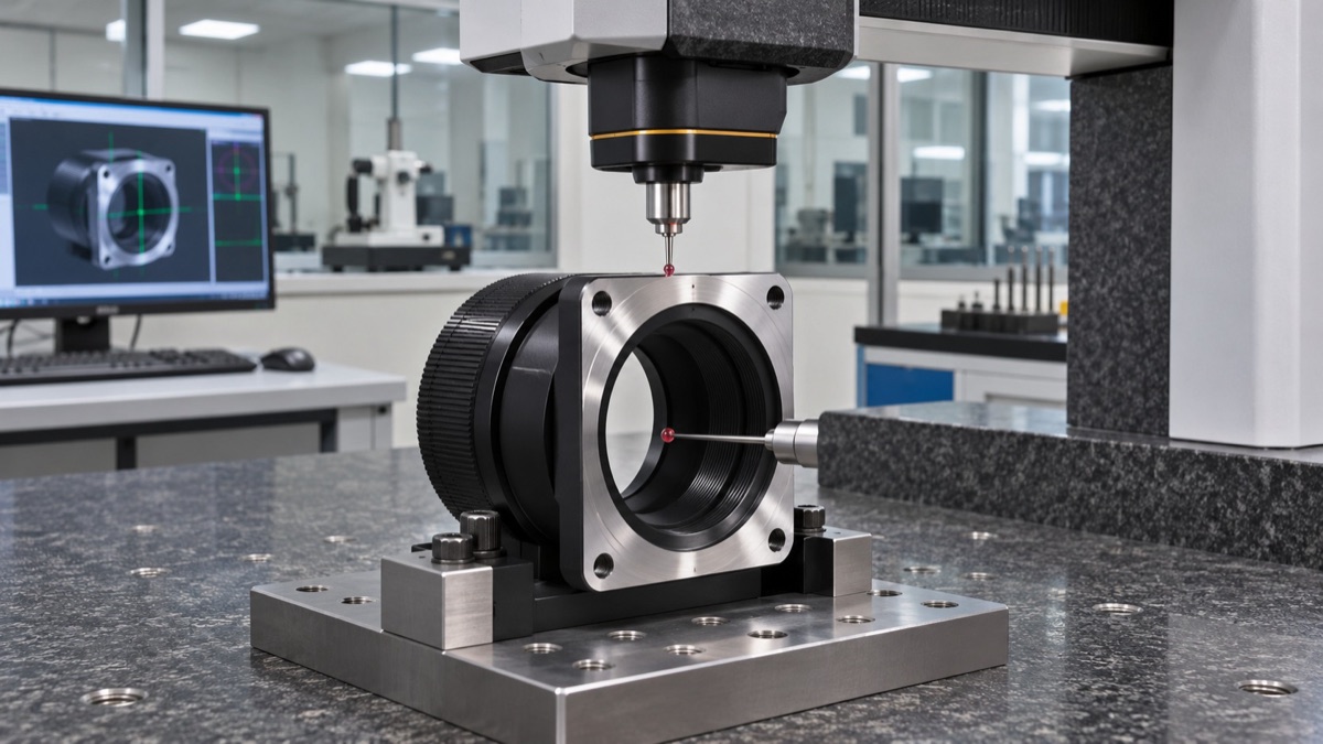
Figure 2: Three-dimensional coordinate review of the spatial relationship between the inner hole, end face and mounting hole of the lens holder.
Black processing should be issued together with size requirements
Optical devices often require a black appearance to reduce stray reflections, but all areas do not lend themselves to being treated in the same way. Whether threads, tight fitting holes, supporting steps and conductive contact surfaces need to be shielded must be clearly stated in the drawing or process description. Otherwise, parts with qualified dimensions before processing may be over-tight, astringent or scratched during the assembly stage after processing.
First article inspection should cover the actual installation status
OEMach recommends that in addition to the size report for the first lens mount, it should also be checked for assembly with a sample lens, camera housing or equivalent inspection tool. This can verify the thread engagement, flange fit and positioning hole relationship, instead of judging whether the part is usable based on the outer dimensions alone.
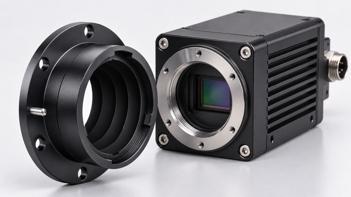
Figure 3: Diagram of the lens holder and industrial camera interface after black processing.
Summary
It is recommended to provide the lens interface standard, camera housing or sensor mounting relationship, key benchmarks and surface treatment range in the inquiry materials. Make the functional relationship clear first so that subsequent processing routes and inspection items will not deviate from the actual assembly requirements.
FAQ
1. Does the lens mount have to be processed using five-axis processing?
Not necessarily. If the key inner hole, flange surface and hole system can be completed through stable clamping, three-axis or four-axis is also feasible; multi-angle interfaces or complex shapes will be more suitable for a five-axis solution.
2. Will black anodizing affect the lens thread?
may affect. Whether the threads are processed, masked or dimensioned should be confirmed according to the actual fit method before processing.
3. Which part should the coaxiality be based on?
It should be determined based on the actual optical path and assembly method. Common objects are the inner hole of the lens interface, the sensor mounting surface or the positioning hole system. The selection cannot be based solely on processing convenience.
4. Can I quote with only the lens mount parts diagram?
A preliminary quotation can be made, but it is best to supplement the lens interface, housing assembly and surface treatment requirements, so that the key process judgment will be more reliable.
5. What testing is required for small batches of lens holders?
Prioritize coverage of functional inner holes, flange surfaces, positioning holes and key threads; do trial assembly of mating parts when conditions permit.
Ready to get a quote for your CNC machined parts?
Submit your engineering drawings to qiancj@oemach.com. We support prototype sampling and small-batch production with strict tolerance control.