
Making a multi-angle mounting surface does not mean that the scanning mirror can be quickly aligned after being installed on the device; the mirror surface, adjustment structure and base interface must be controlled around the same set of benchmarks. OEMach can evaluate the five-axis machining and inspection plan based on the assembly relationship, and forward the assembly and adjustment risks to the drawing review stage.
On the drawings of the laser scanning mirror mounting bracket, the most eye-catching ones are often several inclined surfaces, angle holes and lens mounting holes. But what really determines the efficiency of assembly and adjustment is not processing these angles individually, but whether they can maintain a relationship under the same set of benchmarks. If the mirror mounting surface, adjustment threads and external mounting surface are processed with different standards, even if the parts are of acceptable size, they may still need to be repeatedly aligned when installed on the equipment.
This type of structure is suitable for discussing five-axis machining, not because the five-axis itself is more "advanced", but because multi-angle features, lateral holes and spatial relationships need to be established in one or fewer clampings. Whether five-axis must be used should be determined by part structure, critical angular relationships, batch size, and inspection requirements.
Design inputs, machining controls and delivery impact
| Structural features | Processing concerns | Relationship with decoration |
|---|---|---|
| Multi-angle mounting surface | Clamping times and angle reference | Affects the initial posture of the mirror |
| Lateral thread or hole system | Tool accessibility and hole axis direction | Affects the installation of adjusting parts and locking parts |
| Lens or mirror holder | Bearing surface, central relationship and surface protection | Affects optical component positioning |
| External base interface | Positioning surface, hole position and repeated installation relationship | Affects equipment reassembly accuracy |
Slow installation and adjustment is often due to the fact that the benchmark is not designed as a line.
Scanning mirror mounting brackets usually have requirements in three directions at the same time: the mirror attitude determines the direction of the light path, the adjustment mechanism determines the fine-tuning range, and the installation interface on the bottom or side determines how it returns to the device coordinates. If these three parts lack a common master datum, the assembly personnel can only rely on shims, repeated adjustments or on-site repairs to find the position.
A more reasonable approach is to first determine the main mounting surface, mirror reference surface and adjustment direction at the assembly level, and then convert these relationships into machinable and detectable size and shape requirements for the parts.
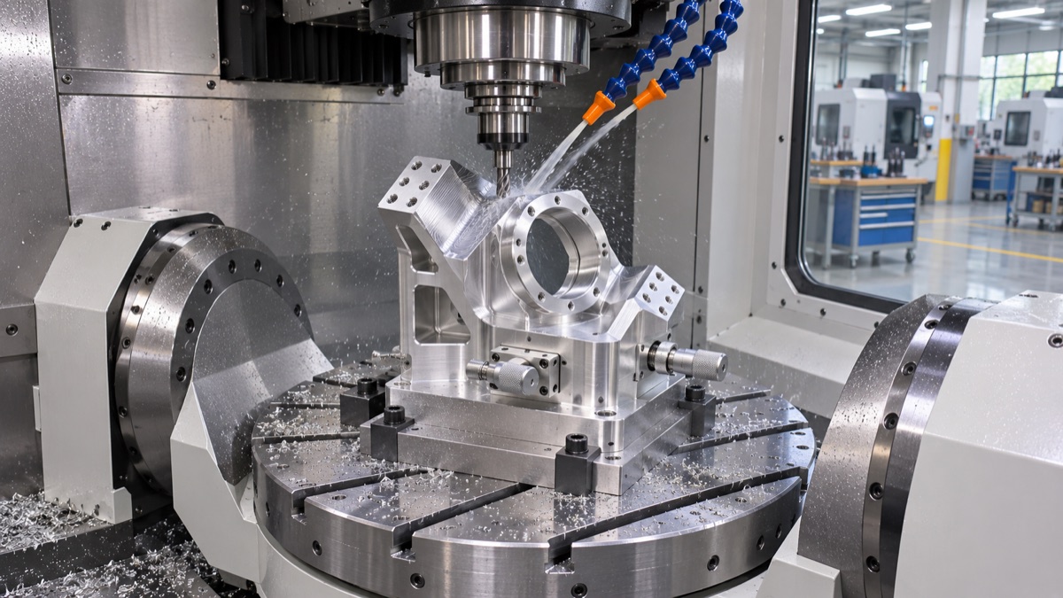
Five-axis machine tool processing multi-angle laser scanning mirror mounting frame
Five-axis machining solves spatial relationships, not all dimensions
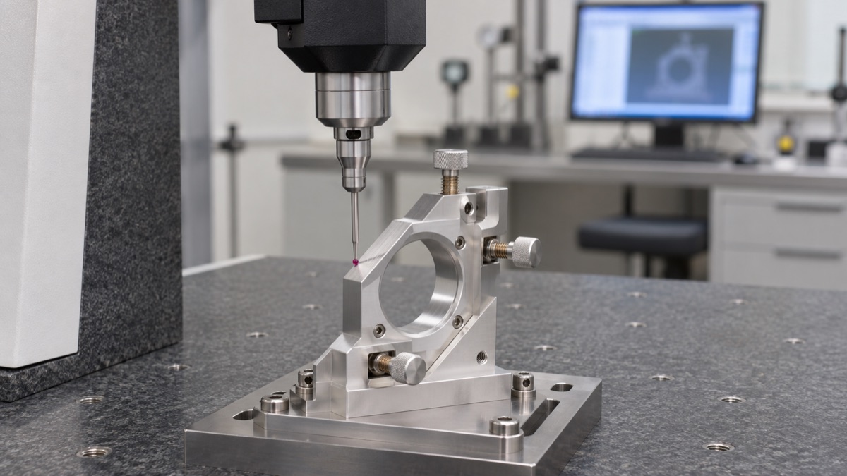
Three-dimensional coordinate review of mounting bracket angle reference and optical interface
One-time clamping is not the goal. The key is to reduce invalid reference conversions.
Even with five-axis equipment, some parts may be turned over due to tool length, fixture obstruction, or surface treatment requirements. The key is not to mechanically pursue "one clamping", but to be able to return to the defined benchmark after each change, and to retain sufficient detection and compensation conditions.
Therefore, during the process review stage, it is necessary to first identify which surfaces are the final assembly surfaces, which holes are used for positioning, and which locations are allowed to be used as process clamping areas. If all surfaces are defined as appearance or functional surfaces, fixtures and processes tend to become passive.
The inspection should end with the assembly posture
For multi-angle mounting brackets, the test cannot only read whether a certain angle is qualified, but also check whether the mirror seat, adjustment axis and base interface are established around the same reference relationship. If necessary, the assembly datum can be used to establish inspection coordinates instead of grabbing each local feature individually.
When OEMach receives an inquiry for such optical structural parts, it can first confirm the key angles, mirror support relationships, adjustment mechanisms and external interfaces based on the assembly model, and then formulate a five-axis or multi-process processing and inspection plan. In this way, installation and adjustment risks can be placed in the drawing review stage in advance instead of being left to on-site installation.
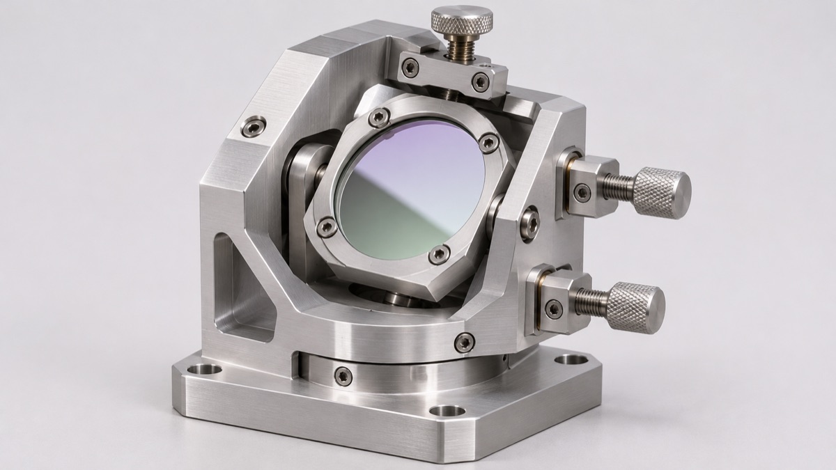
Schematic diagram of the finished laser scanning mirror mounting bracket with adjustment structure
Summary
The value of the multi-angle laser scanning mirror mounting bracket lies in its ability to quickly align and work stably after the equipment is installed. After providing part drawings, mirror parameters, adjustment structures and equipment interfaces, OEMach can assist in the evaluation of DFM, five-axis machining and inspection solutions.
FAQ
Does the scanning mirror mounting bracket have to be processed using five-axis processing?
Not necessarily. If the key features are concentrated on a few planes, three-axis or four-axis with reasonable fixtures may be sufficient; when multi-angle relationships are complex, five-axis is more conducive to reducing datum conversion.
The drawing only shows angles and no reference. Can it be processed directly?
A preliminary assessment is possible, but you should first confirm which mounting surface or axis the angle is relative to, otherwise there will be no unified reference for inspection and assembly.
Will adjusting the accuracy of the thread affect the optical path?
It will affect the adjustment feel, repeatability and stability after locking. The thread, guide relationship and mirror seat reference should also be considered.
What testing is required for the mirror mounting surface?
Usually, it is necessary to confirm the supporting surface, center relationship, angle and related hole positions based on the mirror size and assembly method; the specific project should be based on the design function.
Can small batch projects do one verification first?
Yes. It is recommended to verify the dimensions, installation of key fitting parts and actual adjustment stroke of the first piece at the same time before deciding on subsequent batch plans.
Ready to get a quote for your CNC machined parts?
Submit your engineering drawings to qiancj@oemach.com. We support prototype sampling and small-batch production with strict tolerance control.