
If the lens holder, pressure ring and focusing mechanism are processed according to their respective standards, eccentricity, locking drift or uneven focusing may still occur after the lens is installed. OEMach can sort out the basis based on the relationship between lenses and matching parts before quoting, reducing the repeated assembly and adjustment of small batch proofing.
Just because the lens can be fixed into the lens holder does not mean that the optical structure has a stable positioning relationship. In actual proofing, if the lens is pressed but difficult to focus, the optical axis is slightly offset after locking, or the adjustment stroke is not enough until it is installed on the equipment, it is often not that a certain aperture is made wrong, but that the lens base, pressure ring and focusing mechanism are not designed and processed around the same benchmark.
For procurement and R&D, the optical lens mount is not an ordinary aluminum part. It also undertakes tasks such as lens support, optical axis positioning, focusing, locking, and connection with external equipment. What should be confirmed first is which surface determines the posture of the lens, which hole determines the installation position, and whether the original positional relationship will be changed after the pressure ring is locked.
Design inputs, machining controls and delivery impact
| Part or relationship | Priority confirmation criteria | Common assembly issues | Recommended practices |
|---|---|---|---|
| Mirror holder inner hole and steps | Inner bore axis and bearing end face | Lenses are decentered or tilted | Mark the key dimensions and shape and position relationships at the same time |
| pressure ring | Thread axis and lens holder inner hole | Deflection or uneven force after locking | Confirmed with the lens base as a matching part |
| Focusing mechanism | Guide surface, direction of travel and optical axis | Lateral displacement occurs during adjustment | Provide assembly instructions and travel requirements |
| External mounting interface | Mounting surface and positioning holes | The optical axis is offset after being installed on the equipment. | Clarify the assembly standards of the complete machine |
What really needs to be looked at together is not just the lens diameter
Many drawings only mark the outer diameter of the lens and the size of the inner hole of the lens holder, and then send the pressure ring and focusing seat separately. Each part is easy to process, but the problem is discovered after the assembly is installed: the thread of the pressing ring is inconsistent with the axis of the lens holder hole, and the lens deflects on the step surface; the focusing mechanism uses the other side as the assembly reference, and the moving direction is not completely parallel to the optical axis of the lens.
Therefore, the lens contact step, inner hole axis, retaining ring thread, focusing guide surface and external mounting hole cannot be regarded as five unrelated sets of dimensions. They should be judged back to the same assembly dimension chain.
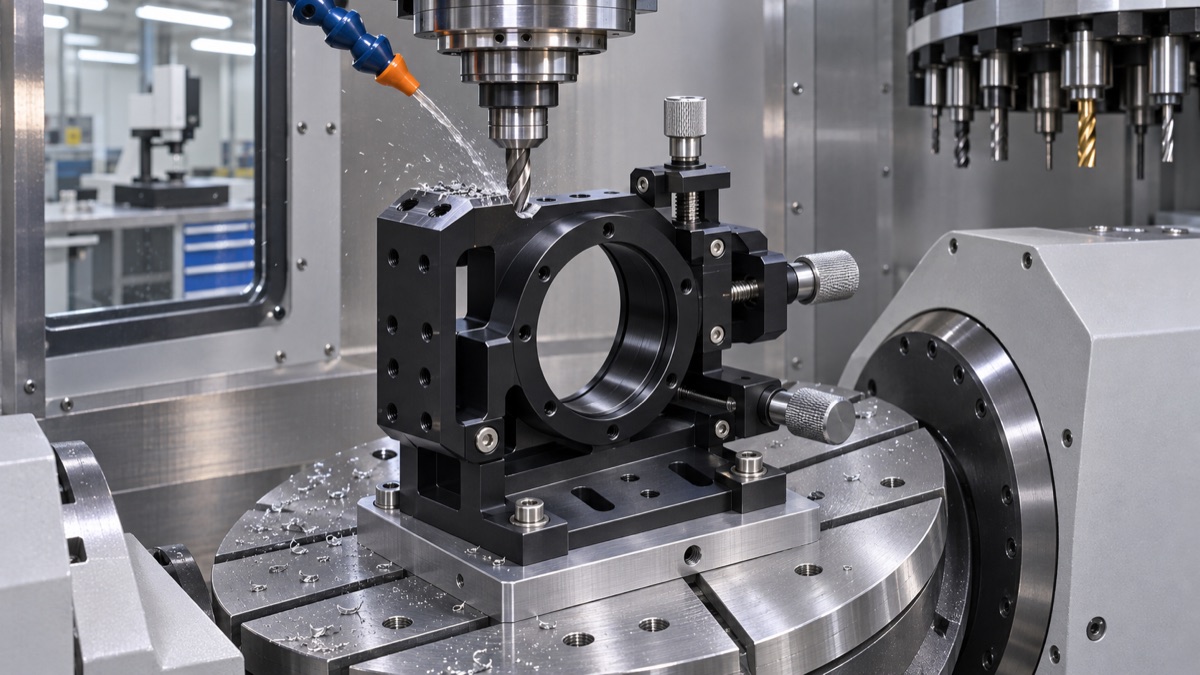
Multi-faceted processing and installation interface control of optical lens holder parts
First clarify who is the main datum, and then decide which parts can be processed separately
Usually, the lens bearing surface and the center hole axis can be used as the main control objects inside the lens holder, and then the external mounting surface or positioning hole is determined according to the equipment installation method. If the pressure ring and the focusing part need to be processed separately, the same set of datums should be referenced in the drawing or 3D assembly relationship, rather than selecting the most convenient clamping surface for each.
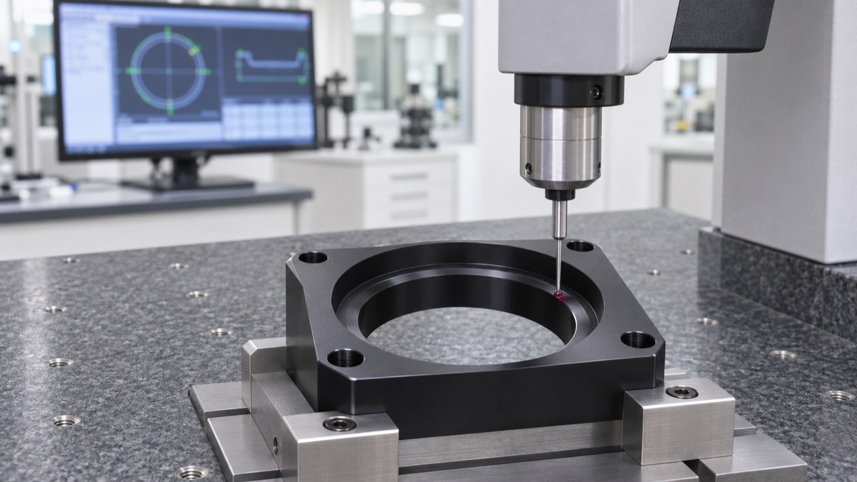
Three-dimensional coordinate review of the inner hole and mounting surface of the mirror holder
Why do pressure rings and focusing mechanisms always go wrong at the end?
The retaining ring seems to be just a threaded part, but it determines the way the lens is stressed. If the ring teeth, chamfering, end face runout and locking force path are not properly handled, the lens may be subject to local stress during locking. The focusing mechanism relies more on the guide relationship: if the direction of the guide rail, guide hole or fine-tuning thread is not based on the optical axis, the adjustment action will become an oblique movement with offset.
This is why the same base assembly is not as simple as putting three parts into one order. It is necessary to clarify the key cooperation relationships into testable and reviewable requirements, and then decide whether one factory will coordinate the processing, or whether the leading party will complete the interface confirmation and then divide the work.
Turn installation and adjustment relationships into processable information
When OEMach receives the lens holder drawings, it is more appropriate to first confirm the lens parameters, ring structure, focusing method, installation position and key inspection items, and then discuss the specific process. For low-volume projects, doing a DFM review and assembly relationship check first can often reduce subsequent modifications more than splitting the quote directly based on part drawings.
When enquiring, it is recommended to provide the outer diameter and thickness of the lens, the ring structure, the fitting model, the installation method, the surface treatment and the installation and adjustment targets. The closer the data is to the actual assembly state, the closer the processing plan can be to actual needs.
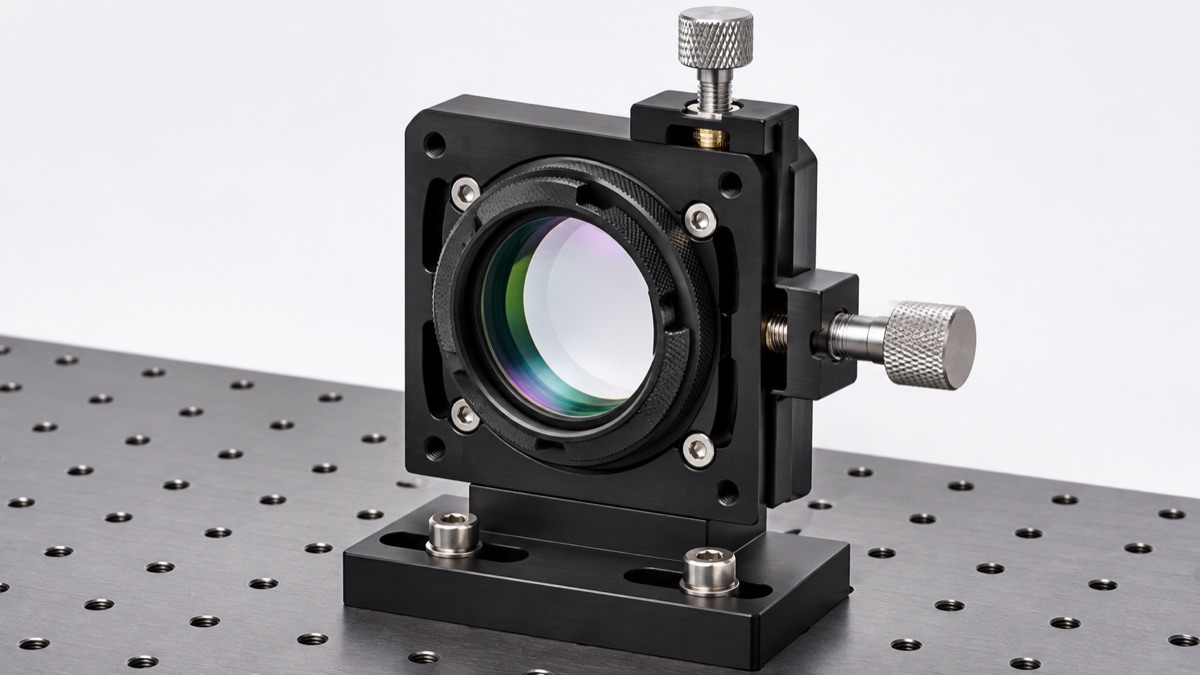
Illustration of the assembly relationship between the lens, pressure ring and fine-adjustment mechanism
Summary
If the project involves the coordination of the lens, pressure ring and focusing mechanism, it is recommended to submit the parts drawing and assembly relationship together before quoting. OEMach can conduct benchmarking, DFM review and small batch processing plan confirmation based on this.
FAQ
Do the lens holder, pressure ring and focusing mechanism have to be processed by the same factory?
Not necessarily, but parts that share optical axes, bearing surfaces or positioning relationships should use the same set of datum definitions and complete the fit confirmation at the first part stage.
I only have the lens size and no complete assembly drawing. Can I quote first?
A preliminary assessment can be made, but the lens thickness, ring ring form, installation interface and focusing method should be supplemented, otherwise the key coordination requirements cannot be determined.
If the inner hole size of the lens holder is acceptable, why might it still affect the imaging?
Outside of the inner hole, the verticality of the end face, step runout, stress on the pressure ring and installation reference will all affect the final posture of the lens.
Will black anodizing affect lens installation?
It may affect the final size of threads, mating holes and bearing surfaces. The size requirements before and after processing of key areas need to be clearly stated in the drawings.
How to arrange inspection for small batches of lens holders?
Priority is given to detecting the lens bearing surface, inner hole axis, external positioning surface and key hole positions; if necessary, the first piece trial assembly can be carried out with assembly accessories.
Ready to get a quote for your CNC machined parts?
Submit your engineering drawings to qiancj@oemach.com. We support prototype sampling and small-batch production with strict tolerance control.