
Define a mechanical bracket without thermal claims
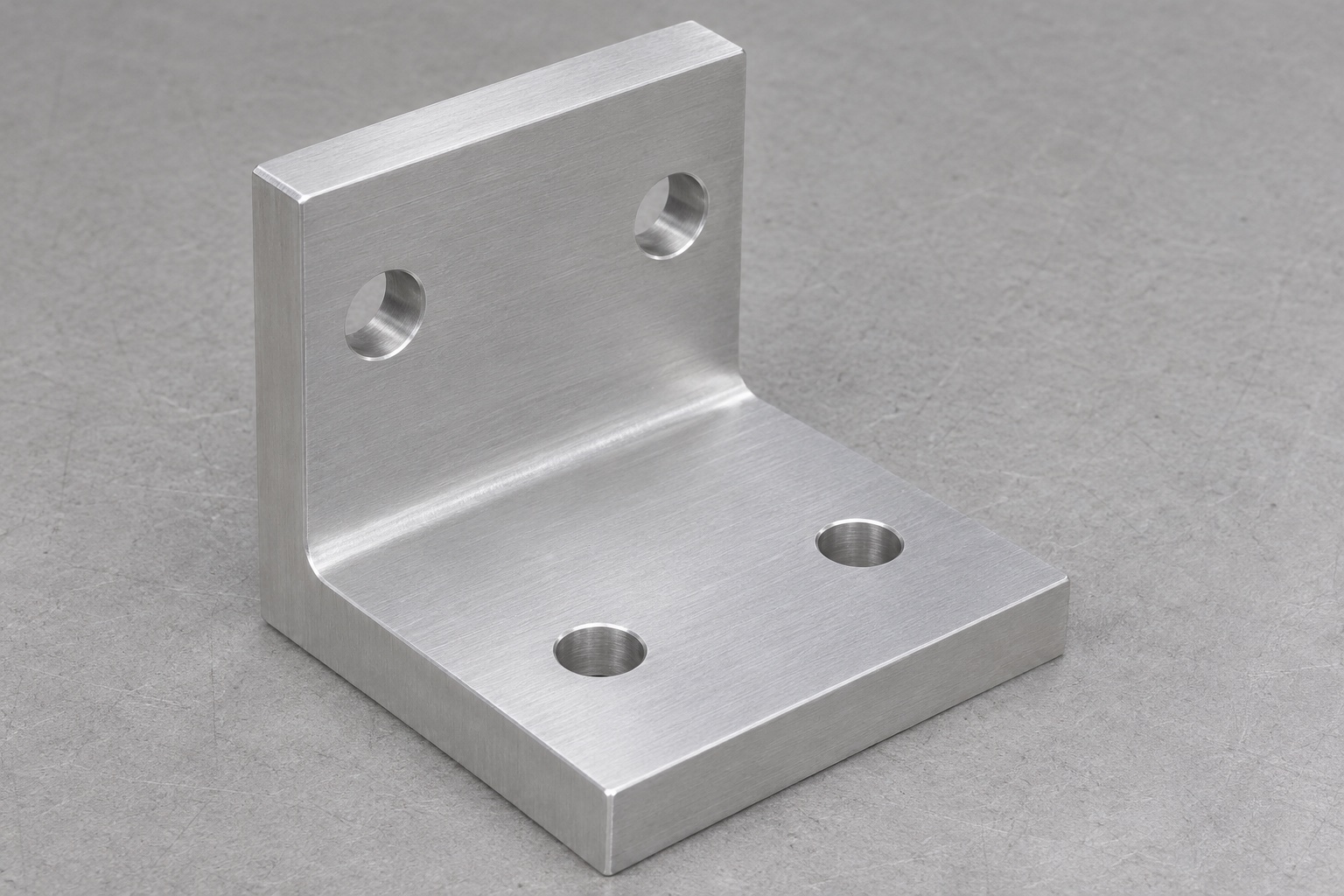
A support angle can locate an inert equipment envelope during service-fixture development. The representative 6061 aluminum bracket here has a rectangular horizontal foot, a rectangular upright and two plain through holes in each plane. It contains no threads, slots or electrical features. Precision CNC milling should distinguish the foot's support function, the upright's locating role and the mounting-hole requirements. This guide concerns a non-operating bench fixture for an ultrasound gel warmer envelope. It does not specify a heater, mounting approval, temperature performance, electrical safety or clinical warming procedure. Those matters require the equipment owner's separate design and qualification process.

Collect the supported envelope before choosing dimensions
Request the controlled envelope, attachment information, connector clearances and permitted contact surfaces. An equipment outline alone may omit a cable exit or removable cover. Identify how the bracket is mounted to the bench and how the dummy envelope is positioned against the upright. Do not assume a convenient hole location is an approved attachment point on a real warmer. The designer must define clearances, retention and loading requirements. The supplier should quote the approved component geometry rather than infer these from the phrase medical equipment support. A limited mechanical drawing review cannot establish suitability for an operating device or a particular clinical installation.
Make the support foot the correct reference
If the foot seats against a fixture base, its supporting face is a likely primary reference. The upright's orientation and the two hole patterns should then relate to the approved datum scheme. Define which edge or feature establishes lateral position and whether any hole actually locates rather than provides clearance. A bracket may be nominally right angled while the working face is tilted relative to its seating surface. Specify the relevant geometric controls rather than relying on an informal ninety-degree label. Inspection should reproduce the intended mechanical relationship and state whether the part is freely supported or restrained in a defined way.
Select identified 6061 stock and supply condition
Specify the alloy, temper, stock form and documentation needed for the actual order. A machined angle from billet and an angle cut from a different stock form may require different preparation even if their final shape looks similar. Preserve material identity and allow enough stock to establish reference faces. Review remaining sections and likely movement before choosing the machining sequence. The material designation does not establish electrical isolation, thermal behavior or compatibility with cleaning chemicals. If additional requirements apply, define them explicitly. Do not attach medical certification or equipment approval to a general aluminum material choice without the necessary supporting evidence.
Rough both planes with stable support
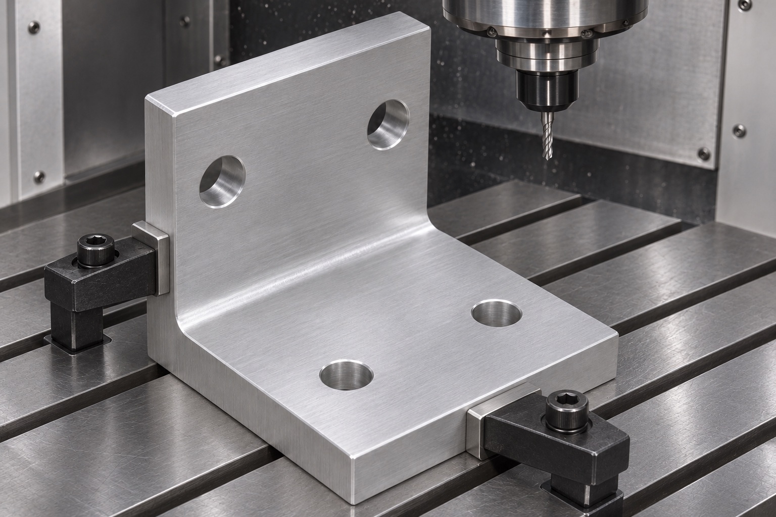
Plan roughing so the foot and upright remain supported while material is removed. Workholding should avoid bending one plane into position and machining the other as if that constrained angle were the supplied geometry. Leave a controlled finishing allowance and consider a release check before the final passes where appropriate. Tool access to the internal corner influences the attainable root radius. The mating envelope must clear that radius or the drawing must provide an approved relief. Do not silently cut a sharp inside corner by hand merely because the CAD model shows an idealized intersection that the chosen cutter cannot produce.
Finish the foot and upright as related features
The seating face, working upright and remaining reference edges form a geometric system. A suitable finishing sequence should preserve their required relationship after release. Inspect local ridges at tool transitions and avoid using a cosmetic outer face as an unapproved reference. Surface finish requirements should identify the actual contact regions rather than impose one unsupported blanket value. A shiny upright does not prove perpendicularity or a flat foot. If the bracket changes shape when unclamped, review material preparation and workholding before tightening tolerances or increasing restraint. The accepted component must satisfy its drawing under the agreed inspection condition.
Keep the four holes and their directions explicit
The foot contains two vertical plain through holes; the upright contains two horizontal plain through holes. Their axes are normal to their respective planes. Distinguish the two patterns in the drawing and inspection report so an inspector does not combine them into an ambiguous flat layout. Screw seats, threads and dowel fits are not part of this representative geometry. Review tool access and drill breakout on both planes. Remove burrs that could lift the foot or alter upright contact. Fastening force must not be used to pull an incompatible pattern into position, and hardware changes require an approved interface review.
Preserve corner clearance during edge finishing
Inspect the internal root, outer handling edges and all hole exits. The corner radius is part of the interface; uncontrolled blending can alter where a dummy envelope first contacts. Break edges only to the specified requirement and protect the mounting faces from abrasive damage. Clean chips and residue from the corner and holes before packing. Ordinary protective preparation is not a validated medical cleaning process. If a surface treatment is ordered, settle masking and final acceptance conditions before machining. Coating can affect holes and seating even when its visual purpose appears decorative, so it should not be added informally after dimensional release.
Inspect the angle using defined support
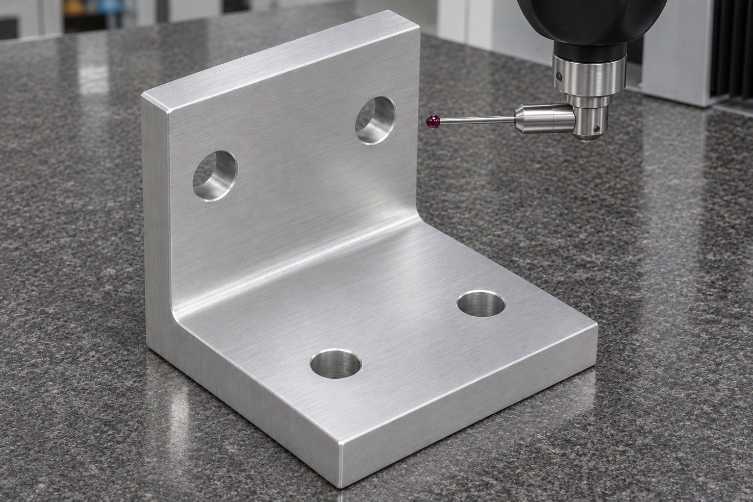
Seat the bracket on the specified reference face without concealing burrs or forcing it flat. Measure foot form, upright orientation and the required relationship of the working surfaces. A coordinate or suitable mechanical method can inspect the hole patterns in their distinct planes. Probe access to the internal corner should be reviewed before promising a particular measurement. Keep edge breaks and fillets out of reference-plane fitting where the drawing requires it. A simple square provides a limited observation, not necessarily the full geometric evidence. Record the instrument, setup and actual results so incoming inspection can reproduce the intended evaluation.
Use an inert envelope in an unloaded fixture
An identified dummy equipment envelope can supplement inspection by revealing interference at the upright, root radius or fastener arrangement. Record all revisions and the bench support condition. The trial should remain non-operating and should not use heater performance or a live electrical assembly as evidence of bracket acceptance. If mounting changes the apparent angle, inspect the base support and fasteners before reworking the upright. A successful mechanical fit does not establish temperature stability, safe use, load capacity or approval for mounting an actual gel warmer. Those outcomes remain outside the component inspection and require separate responsible evaluation.
Diagnose rocking and first contact before rework
If the foot rocks, check retained burrs, support cleanliness and measured form. If the dummy contacts only one edge of the upright, review the reference envelope and face orientation rather than widening every clearance. If a fastener binds, check the appropriate pattern and screw geometry. Record the first interference and the related dimensional result before removing material. An authorized correction should address the confirmed cause and be followed by reinspection. A conforming bracket should not be altered merely to accommodate a fixture or dummy whose revision differs from the approved design. Keep the original observation available for engineering review.
Quote the complete machined bracket scope
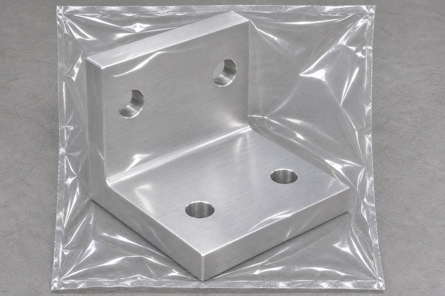
Provide controlled drawing and CAD revisions, alloy and temper, quantity, mating-envelope information, mounting hardware requirements, finish and inspection deliverables. Identify whether an inert dummy or dedicated fixture is supplied by the buyer. Separate machining, first-article reporting and special tooling costs where appropriate. Pack the angle so the foot and upright cannot be bent by straps or loose components, and protect the defined contact faces from scratches. Maintain material and revision identity with the release records. This creates a verifiable custom medical equipment mounting-parts scope while leaving thermal, electrical and complete installation qualification with the responsible equipment organization.
FAQ
Does the bracket define gel warming performance?
No. It is a mechanical fixture component. Heater control, temperature performance, electrical safety and clinical use require separate design and qualification.
Are the four holes in one plane?
No. Two holes pass through the foot and two through the upright, with axes normal to their respective faces. Inspect the two patterns explicitly.
Does a nominal right angle prove working-face orientation?
No. Define the relevant support and working faces and their geometric relationship. A general angle label cannot replace a controlled datum scheme.
Why review the internal corner radius?
The mating envelope must clear that radius to seat as intended. An idealized sharp CAD corner may not match the selected milling process.
Can tightening screws remove a foot-flatness error?
It may restrain the shape but does not prove drawing conformance. Use the agreed free-state or defined restrained acceptance condition.
What does the dummy fit confirm?
Only the observed mechanical seating and clearance in that identified non-operating setup. It does not establish load capacity or operating device approval.

tanghangyun@oemach.com