
Define a bushing rather than a safety assembly
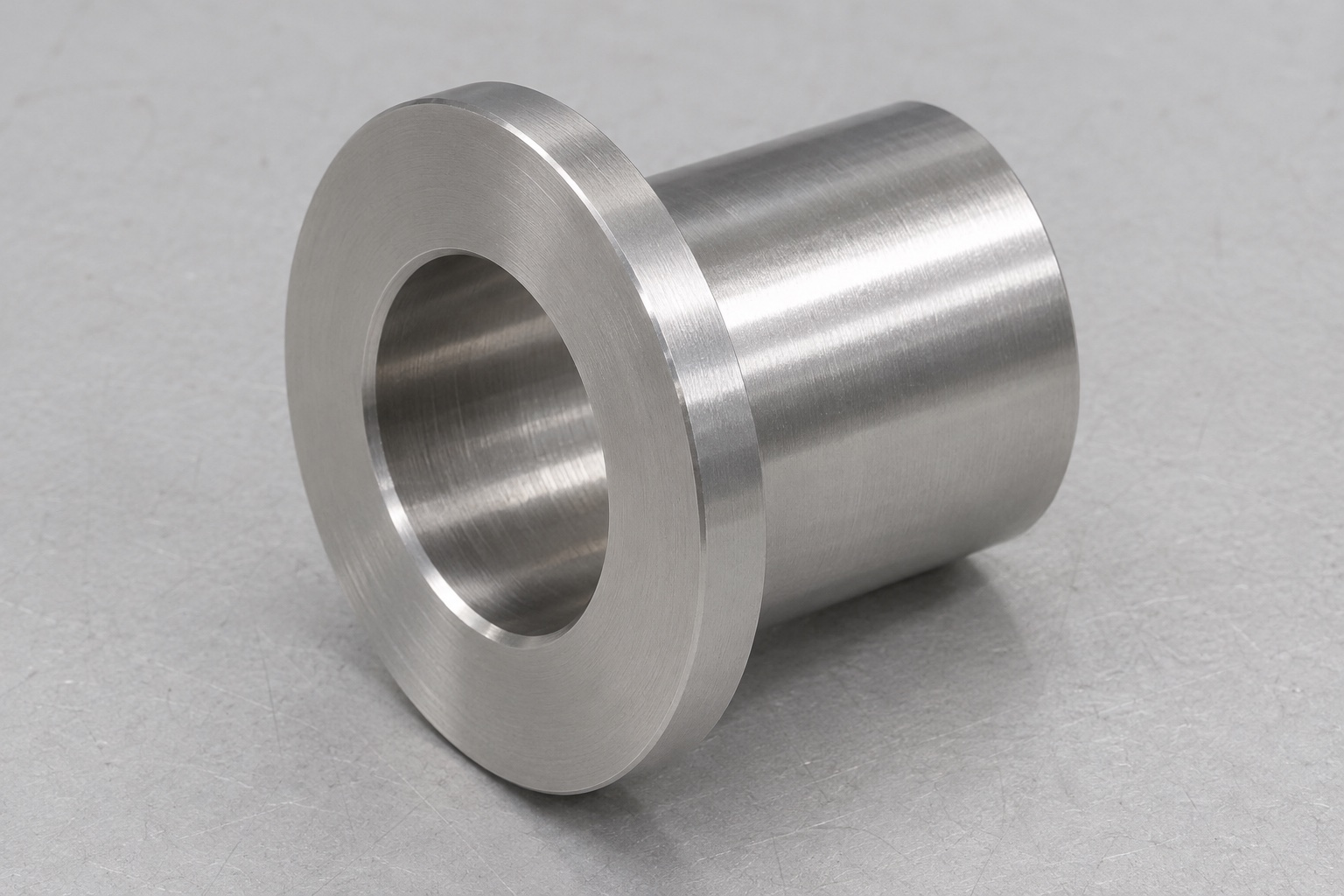
A flanged sleeve bushing can provide a defined mechanical interface in a laboratory centrifuge lid service fixture. The representative part here has a smooth cylindrical barrel, a circular flange and one concentric axial through bore. It has no oil groove, thread or secondary hole. Precision CNC turning should identify which cylindrical surface locates the part and which face establishes axial seating. This guide concerns an unloaded, non-operating bench assembly with an inert hinge pin. It does not specify an operating replacement, a rotor part or a lid interlock, and it makes no claim about containment, service life or centrifuge safety.

Separate the inner and outer interfaces
The bore mates with a defined pin, while the barrel fits a separate housing or fixture. Their fit requirements must be specified independently. A pin that moves through the bore does not show whether the outside diameter seats correctly in its housing. Request the mating envelopes, insertion direction and installed support condition. The designer must state whether the bushing is retained by a specified fit or by another assembly feature. Do not select interference, lubricant or installation force from a generic bushing name. Those decisions belong to the approved interface design and must not be invented during quotation or machining.
Establish the relevant cylindrical datum
Choose the reference axis according to the assembly's actual locating surface. If the barrel establishes location, the bore and flange face may need requirements related to that axis. If the bore is the primary reference, inspection should reproduce that relationship instead. Size, cylindricity, coaxiality and face orientation are different characteristics and should not be compressed into one informal concentricity statement. A correctly sized bore can still be tilted relative to the barrel. The drawing should state the required geometric controls, measurement length and acceptance condition so that supplier and buyer evaluate the same functional relationship.
Specify 316L stock and traceability
Identify the required 316L grade, stock form and supply condition before programming. Preserve the material lot from incoming stock through parting and secondary operations. A visually similar stainless remnant is not a substitute for an identified material specification. Provide sufficient allowance to establish reference surfaces without leaving an unnecessarily slender unsupported section. Additional chemical or documentation requirements should be agreed in the order. The alloy name alone does not prove cleaning compatibility, corrosion behavior in a particular environment or certification for medical equipment. Those application requirements need their own evidence and remain distinct from dimensional acceptance of the machined sleeve.
Turn related features in a coherent sequence
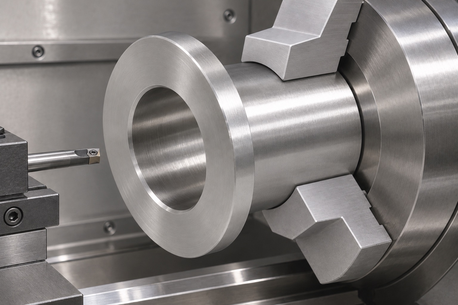
Where access permits, establish the barrel, bore and a relevant flange face from a common setup. That can simplify control of their relationship, but a single setup is not automatically the best route for every geometry. Review stock grip, tool reach and the section remaining after boring. Leave a controlled allowance where a later setup is necessary. Suitable tooling and chip evacuation help avoid rubbing, built-up material and recutting marks in stainless steel. The process must be verified on a released physical part; machine coordinates and a successful simulation do not demonstrate the actual bore and flange geometry after unclamping.
Finish the bore along its useful length
The through bore should meet its drawing requirements throughout the specified engagement length, not only at the entrance. A long or flexible boring tool can produce taper or local form error. Select an appropriate machining and measurement strategy for the actual bore size, finish and accessibility. Reaming, boring or another approved process should be chosen for controllable results rather than appearance. Keep entry chamfers separate from the working cylinder in inspection. Do not hand-polish a bore until one uncontrolled pin fits, because that can change the local size and conceal a form problem without establishing the intended geometric relationship.
Control the flange seat and shoulder transition
The flange provides an axial stop only when its intended seating face contacts the mating reference. Define face orientation, thickness and the shoulder radius between flange and barrel. The housing must clear that radius if full seating is required. A flange can appear flush while resting on a corner or burr. Check the seat using suitable dimensional methods rather than judging a reflected light band. Avoid reducing the shoulder radius informally to solve a mating-part conflict. A geometry change should be approved and assessed against the required remaining section, tool access and final inspection method before rework proceeds.
Plan secondary holding without deforming the sleeve
Parting and opposite-face finishing may require a second setup. A soft collet, split bush or other suitable fixture can distribute contact, but workholding still needs safe retention. Excessive gripping may temporarily distort the barrel or bore, while insufficient gripping permits motion. Document how the reference axis is recovered and which surfaces must remain free of jaw marks. Check the released condition after finishing. Do not accept a dimension measured only while the sleeve is constrained inside its machining fixture. The actual holding method should be proven for the drawing, material and wall section rather than copied from an unrelated cylindrical part.
Deburr and clean the through passage
Inspect both bore entrances, the flange rim and the shoulder transition for loose material. Remove burrs while preserving the specified edge breaks and useful cylindrical length. A large hand chamfer can reduce engagement or alter the axial seating area. Clean the through passage so chips and residue are not trapped before packing. Keep stainless components away from contaminating swarf during finishing. If passivation or another treatment is ordered, define its documentation and the final acceptance stage. Ordinary protective cleaning should not be described as sterilization or validated laboratory decontamination unless that additional process is explicitly specified and supported by separate evidence.
Inspect size and geometric relationships separately
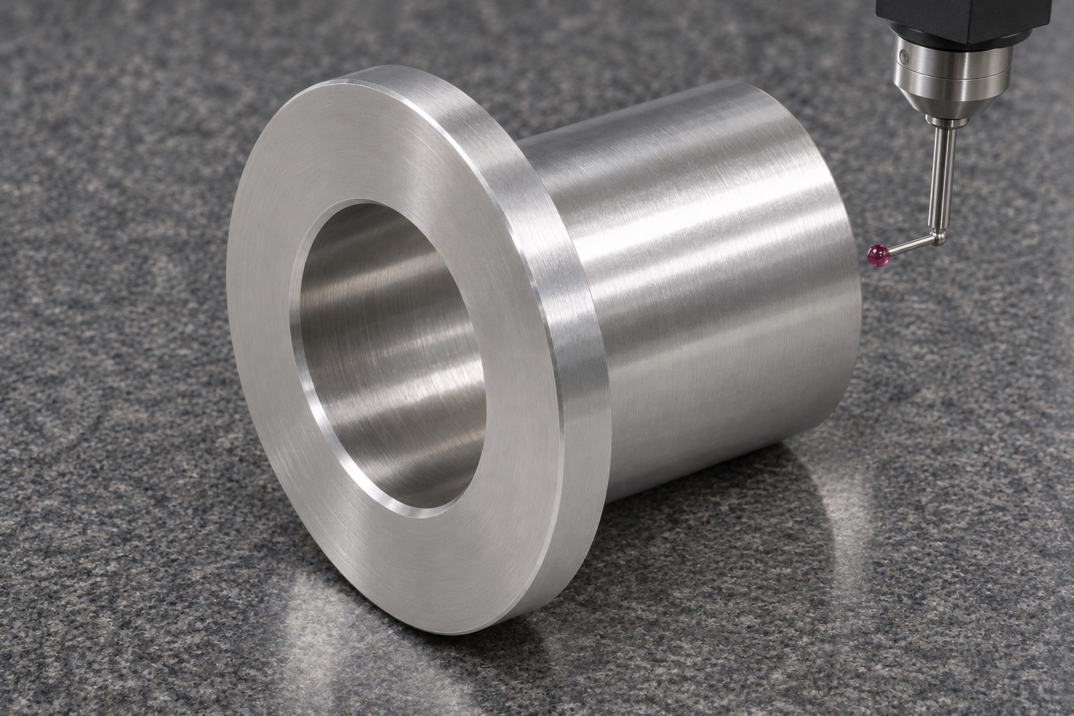
Measure bore and barrel sizes at appropriate axial stations and orientations. Select instruments with suitable access and contact force for the actual section. Check flange-face orientation or runout using the drawing's defined axis, avoiding a setup that merely reproduces chucking error. Record the support condition and measurement method. A pin gauge is useful for its specified size check but cannot establish every positional or form requirement. If results disagree, compare reference alignment and instrument setup before changing the part. An inspection report should connect each measured characteristic to a controlled drawing revision and an actual produced component.
Keep the inert fit trial limited
An identified dummy pin and housing reference can supplement inspection in a non-operating bench fixture. Record their revisions, orientation and seating sequence. Observe insertion and removal without adding service loads or altering an actual centrifuge safety mechanism. A smooth movement does not establish fatigue life, lid retention, interlock function or safe operation. If seating fails, identify whether the first contact is at the barrel, flange shoulder or bore entrance. Review the mating references as well as the bushing. Rework should address a confirmed cause and receive approval, not enlarge every interface until one uncontrolled sample can be assembled.
Send an RFQ that defines the whole component
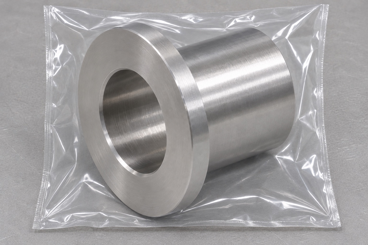
Provide matching drawing and CAD revisions, material specification, quantity, pin and housing information, geometric controls, final surface state and inspection deliverables. Identify any permitted markings and protected surfaces. State who supplies the inert references and whether first-article reporting or fixture development is included. Protective packaging should separate parts so the flange seats and bore edges cannot strike loose hardware. Maintain material and revision identity with the release records. This gives a verifiable scope for custom laboratory equipment bushing machining while leaving operating replacement approval, complete hinge design and centrifuge qualification with the responsible equipment organization.
FAQ
Is this an approved operating centrifuge replacement?
No. The discussion concerns a representative non-operating service fixture. It does not approve a replacement, rotor component, lid interlock or safety assembly.
Does a passing pin prove bore alignment?
No. A pin checks a limited fit or size condition. Bore orientation and relationship to the barrel require the drawing's specified geometric inspection.
Which surface should define the reference axis?
Use the surface that establishes location in the approved assembly. The drawing must make that choice explicit instead of leaving it to inspection preference.
Why inspect the flange shoulder radius?
The mating housing must clear the shoulder for full seating. A corner conflict can leave a flange apparently flush while preventing intended face contact.
Can heavy chucking hide a bore problem?
It can change the constrained shape. Verify the supplied geometry in the drawing's agreed released or restrained condition after machining.
What does an inert hinge trial establish?
Only the observed mechanical fit with identified references. It does not demonstrate fatigue life, lid containment, interlock function or operating centrifuge safety.

tanghangyun@oemach.com