
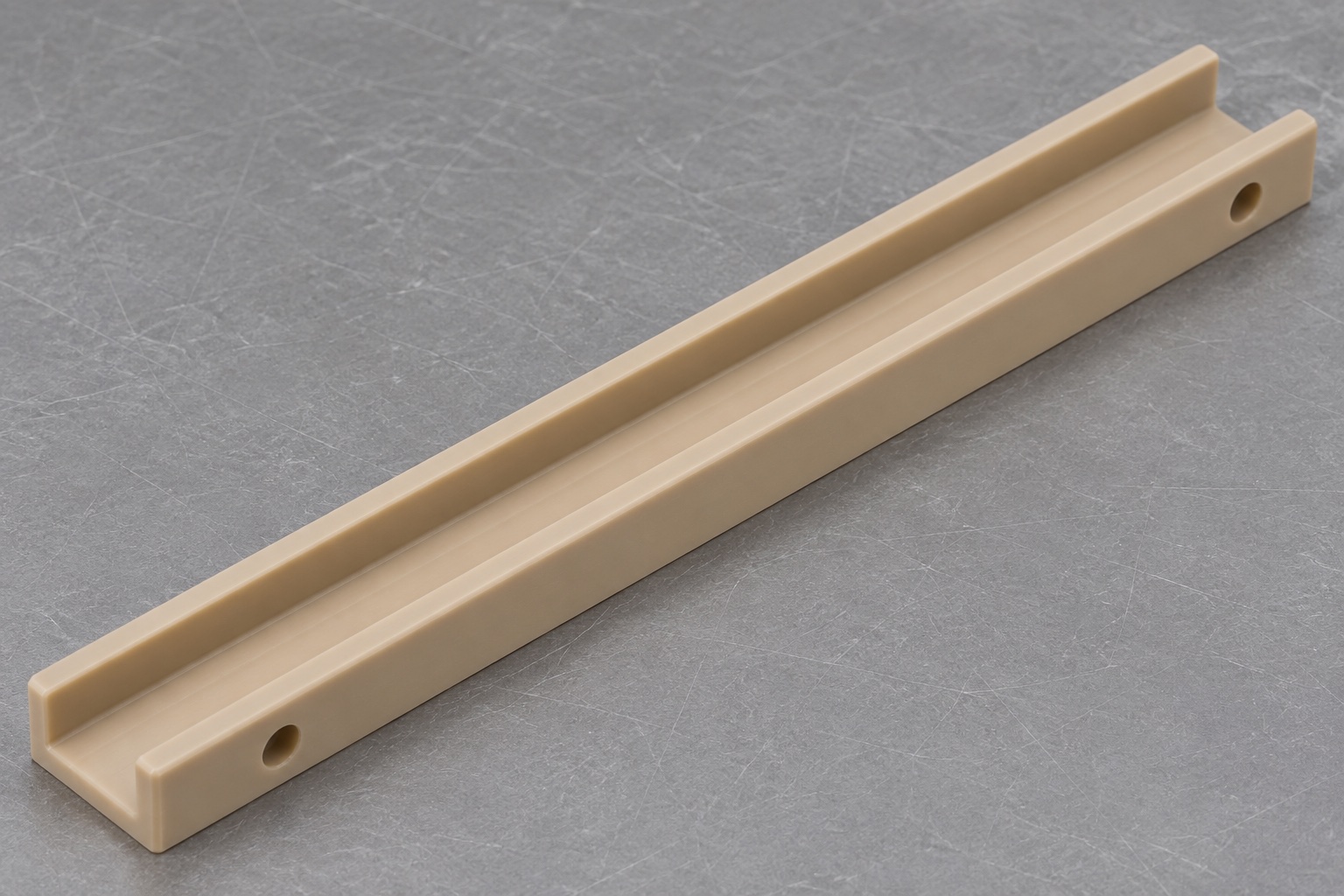
Define the liner and its limited mechanical role
A histology tissue embedding cassette feeder can use a separate liner to guide an identified cassette envelope. The representative PEEK part here is a long rectangular U-channel with a flat floor and two straight walls, open at both ends. Two plain horizontal mounting holes pass through the same outer wall near its ends. Precision plastic machining should start with the cassette path, mounting interface and acceptable contact regions. This guide covers a non-operating bench assembly using inert cassette references. It does not establish specimen handling performance, analytical results, embedding quality, chemical compatibility or suitability for a complete clinical laboratory workflow.

Use a controlled cassette envelope
Request the cassette's maximum relevant envelope, edge geometry, permitted orientation and any features that must clear the channel. A nominal width may omit a lid overhang, hinge detail or local projection. Define the path at entry, along the guide and at exit rather than checking only a stationary section. Different cassette revisions should not be mixed into one undocumented fit reference. The responsible equipment designer must set clearance and contact requirements. A machining supplier should not infer acceptable sliding force, feed reliability or specimen protection from a generic cassette photograph. Mechanical drawing acceptance and feeder qualification are separate activities.
Relate floor and walls to the mounting reference
The floor supports the cassette envelope while the walls limit lateral movement. Define how these features relate to the installed mounting surface and the direction of travel. A channel can have the correct width at one point while its floor twists or its walls taper along the length. The drawing should identify the relevant straightness, parallelism or profile requirements using suitable specifications. Inspection instructions must say whether the part is measured freely supported or in a defined restrained condition. A thin liner pulled straight by a fixture does not necessarily represent the released component that will be supplied to the buyer.
Specify the actual PEEK grade
PEEK is a material family, not a complete purchase specification. Identify the approved grade, filler condition, stock form and any documentation required by the order. The representative part uses natural unfilled PEEK, not a visually similar polymer or an unspecified reinforced grade. Retain identity through cutting and keep remnants traceable. General material familiarity does not establish compatibility with a particular reagent, cleaning procedure or specimen-handling application. Those requirements need separate assessment using actual material and process information. Do not label a machined liner medical grade or biocompatible without the specific requirements and supporting evidence that would justify such a statement.
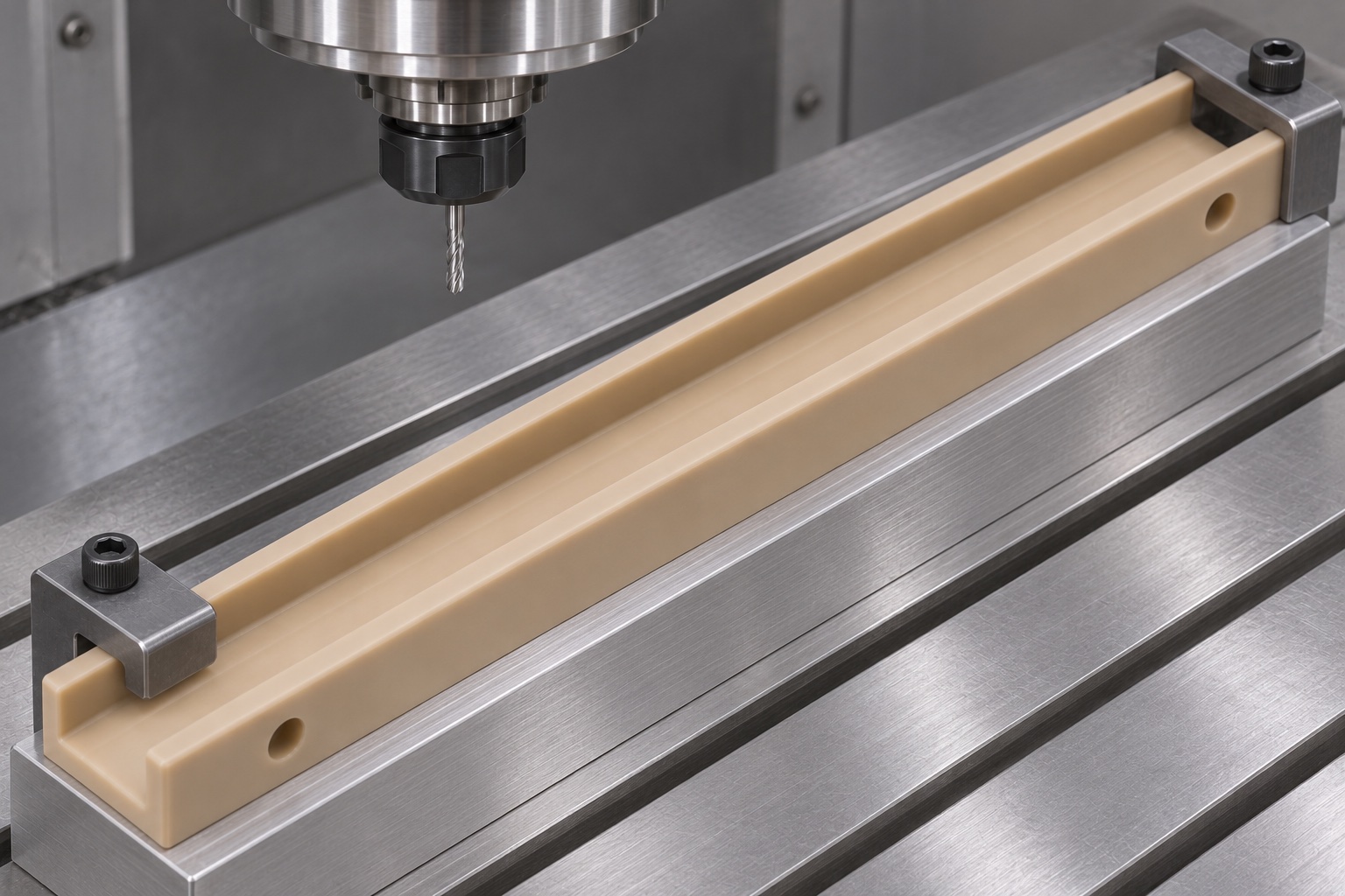
Rough the channel with balanced support
Prepare reference faces while the blank remains sufficiently stiff. Rough the long open channel with an allowance for finishing, taking account of the remaining floor and wall sections. Workholding should support the body without squeezing the walls into an artificial width. A release and reclamp step may reveal movement hidden during cutting, but its need depends on the actual stock and geometry. Suitable sharp tools and chip evacuation help avoid rubbing, heat buildup and damaged edges. There is no universal cutting schedule implied here. Confirm the selected sequence through inspection of physical trial parts under the agreed measurement condition.
Finish the travel path rather than a local width
Plan the floor and wall finishing operations around the full cassette path. Tool transitions, local ridges and end-edge treatments can influence first contact even when a caliper reading at the midpoint looks acceptable. The open ends should provide the approved entry and exit geometry, not an improvised lead-in created by hand sanding. Check that the cutter can achieve required corner radii without leaving incompatible material at the floor-wall junction. Preserve the contact region defined by the drawing. A visually smooth channel should not be treated as proof of uniform clearance, free-state straightness or reliable feeding in an operating laboratory instrument.
Keep side-wall holes separate from the travel envelope
The two representative mounting holes are horizontal through one side wall, not vertical through the floor. Their location must be defined from approved references with adequate remaining material around them. The design must also show how the fastener arrangement avoids unwanted protrusion into the cassette path. Plain holes do not define a screw-head seat or thread engagement by themselves. Do not add countersinks or enlarge the wall opening simply to fit available hardware. Review tool access and drill breakout, then inspect the channel-side exits for burrs. Hardware compatibility is an interface requirement to settle before machining, not an assumption to repair afterward.
Deburr channel exits and hole intersections
Inspect both open ends, wall tops, floor transitions and the inner exits of the mounting holes. Thin plastic strands can remain attached where a hole meets the channel. Remove them without smearing material into the opening or rounding the wall enough to change guidance. Protect the defined contact surfaces from uncontrolled abrasive blending. Use appropriate lighting and magnification to distinguish a burr from acceptable machining texture. Cleaning should remove chips and process residue to the agreed condition. It must not be described as validated laboratory decontamination or sterilization unless that additional process is explicitly specified and supported by its own evidence.
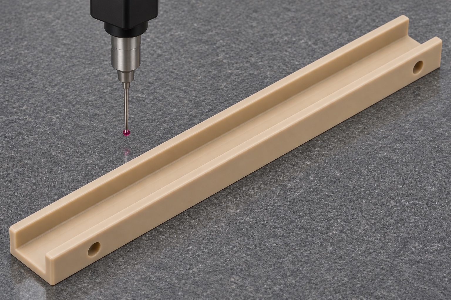
Condition before released-state measurement
The long plastic shape should reach the agreed inspection environment before final acceptance. Temperature and measurement force can influence the observed dimensions, and local clamping can conceal bow. Use a documented support arrangement and suitable low-force or noncontact methods where necessary. Measure channel width at multiple stations, and inspect floor and wall relationships from the approved datums. Check hole location separately from the fit of a particular screw. A set of isolated size readings does not establish the whole travel profile. The inspection report should identify conditions and methods so results can be compared meaningfully with a later incoming inspection.
Use an inert travel check as supplemental evidence
An identified inert cassette reference can be moved through the non-operating channel in the approved orientation. Record the reference revision, mounting condition and points of first contact. Observe entry and exit as well as the middle section. This limited trial does not prove automatic feed reliability, specimen protection or analytical performance. Do not force a reference through a bind or lubricate the channel without authorization to conceal interference. If contact changes after mounting, review wall distortion and the fastener arrangement before altering channel width. A controlled drawing and dimensional inspection remain the basis for component acceptance.
Diagnose local binding before removing material
A bind near a mounting hole may indicate an inner burr or an unintended fastener projection. Binding over the whole length may reflect a cassette-envelope mismatch, channel width or wall alignment. An end-only problem may come from the entry geometry or a bowed liner. Rotate or substitute references only within the approved diagnostic plan, keeping each revision identified. Record observations before rework. Widening the entire channel can hide a local issue while allowing too much lateral movement elsewhere. Any approved change should include reinspection of affected dimensions and an updated record of the final accepted condition.
Quote a complete laboratory fixture component
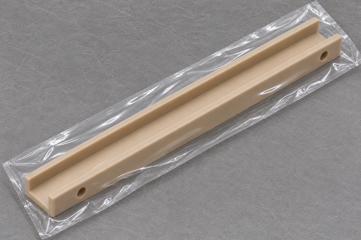
Supply matching drawing and CAD revisions, PEEK grade, quantity, cassette envelope, mounting details, final surface condition and inspection deliverables. State whether the buyer provides inert references and whether a dedicated travel fixture is part of the order. Clarify cleanliness, packaging and identification requirements without implying sterile supply. Pack the liner with support along its length so the walls and floor are not bent by straps or loose hardware. Keep contact surfaces separated from abrasive materials. This creates a clear scope for custom medical laboratory equipment parts while leaving reagent compatibility, operating performance and complete feeder qualification with the responsible equipment organization.
FAQ
Is a cassette's nominal width enough to define the channel?
No. Lid edges, projections, orientation and revision can affect the travel envelope. Use controlled mating geometry rather than one nominal width.
Do the mounting holes pass through the floor?
No. This representative liner has two horizontal holes through one side wall. Their exits and the fastener envelope must remain compatible with the cassette path.
Why inspect the liner outside its machining fixture?
Clamping can conceal bow or squeeze the walls. The agreed free-state or restrained inspection condition must represent the drawing's acceptance requirements.
Does unfilled PEEK prove reagent compatibility?
No. The exact grade and actual exposure conditions require separate assessment. Material family alone does not establish compatibility with a laboratory process.
Can a smooth manual travel check prove feeder reliability?
No. It supplements mechanical inspection only. Automated feeding, specimen handling and analytical performance require separate qualification and evidence.
Why inspect the inner hole exits closely?
Loose plastic strands or burrs can remain where holes enter the channel. They may interfere locally even when the main channel dimensions are correct.

tanghangyun@oemach.com