
Define the receiver and the latch separately
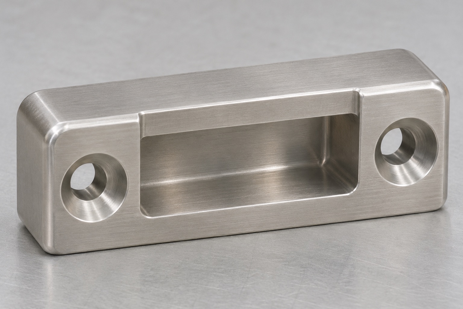
A transport basket for medical instruments may use a separate receiver block that accepts a latch tongue. The example here is a rectangular 316L block with a shallow open front pocket and two countersunk mounting holes flanking that pocket. The pocket's upper contact surface presents the engagement edge; the rear face seats against a bracket. The receiver alone is not the complete latch or basket. This guide covers machining and inspection for an unloaded development assembly. It does not define safe load, retention strength, infection control or a cleaning procedure. Begin with a section showing the actual latch path and contact order.

Establish the engagement envelope
Ask for the latch tongue thickness, width, entry trajectory and required clearance around its corners. A nominal rectangular coupon may check pocket size but omit the rotation of the actual mechanism. Define the working overlap separately from entry clearance, because a tongue may enter a pocket and still fail to engage the intended contact surface. Check the path for release as well as closure. Identify which face stops the tongue and whether a separate basket feature limits travel. Do not make the pocket deeper simply to resolve an interference whose cause is a misplaced receiver or an incompatible latch revision.
Set the mounting datums before sizing the pocket
The rear mounting face can be the primary datum when it seats directly against a bracket. Use a side or end reference actually present in the assembly to define lateral and vertical location. Countersunk screws can draw a block toward their centers, so confirm whether their geometry locates the part or merely attaches it. A pocket offset from a cosmetic perimeter does not necessarily protect the installed engagement height. Put the chosen references in the drawing and report. Distinguish the floor depth from the height of the upper contact lip, and specify where to measure away from corner fillets.
Rough a supported stainless blank
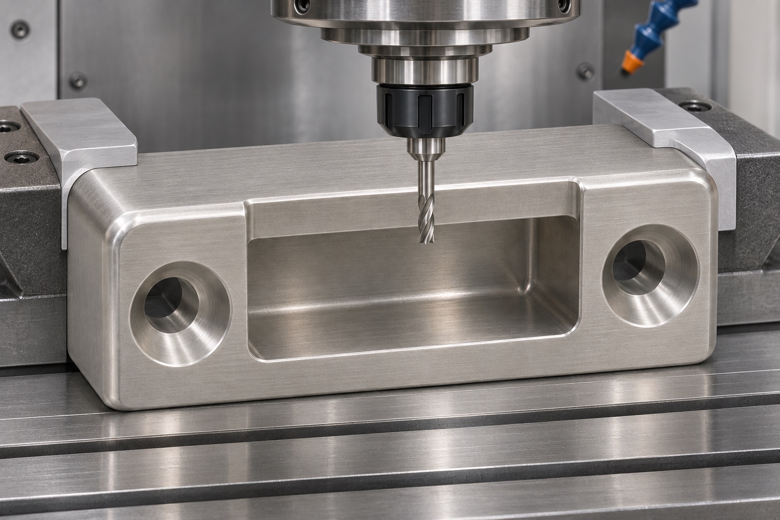
Specify 316L stock condition and keep its material lot linked to the job. Prepare a stable rear face and clamp along a rigid section, clear of the front pocket. Rough the recess while enough material supports the engagement surface. Use tools with adequate chip space and reach for the approved corner radius. Avoid rubbing a stainless surface with a dull or unloaded cutting edge. Where the pocket is deep relative to its opening, plan chip evacuation and inspect for recutting marks. The finished shape should be measured after release, not accepted from a dimension taken only while the blank is held under cutting load.
Finish contact faces deliberately
A pocket can meet overall width while leaving a local ridge that shifts first contact. Finish the working lip, side clearances and back wall according to their separate functions. Keep tool transitions away from the functional edge when possible and qualify the finished corner radius on a pilot. A theoretical sharp internal corner may not be achievable with the chosen cutter; resolve the mating corner geometry rather than silently adding hand relief. Leave specified material at the lip and do not reduce its section to improve the visual opening. Any strength requirement belongs to the designer's separate mechanical evaluation, not to an attractive machining finish.
Match the countersinks to the specified screws
Check screw head angle, diameter and required seated height before setting countersink depth. A head can look flush while contacting only a narrow ring if the form is wrong. Verify the seat with the appropriate gauge or a controlled screw example where the inspection plan allows it. Review the material remaining between a countersink and the pocket when proposing a deeper recess. Remove burrs at both rear hole exits, since they can tip the receiver on its bracket. Record which surfaces are permitted to show tool marks. Do not compensate for an incorrect fastener by changing a conforming receiver without authorization.
Separate deburring from surface treatment
Inspect the pocket mouth, upper engagement edge and screw holes under suitable lighting. Remove raised material while preserving the specified edge break and usable contact band. Broad hand rounding can change overlap and move the point at which the tongue catches. Keep stainless components separated from ferrous swarf and clean the recess so no chip remains behind the lip. If passivation or another finish is required, specify the route and final acceptance condition. The alloy designation does not establish cleanliness, compatibility with reprocessing chemicals or corrosion performance in a particular environment. Those requirements must be defined and verified separately.
Measure the pocket from the mounting references
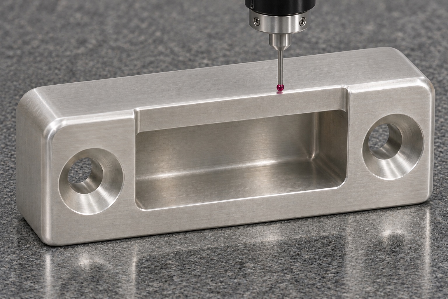
Seat the block without distortion and establish the defined datum arrangement. Measure pocket depth, lip position and useful opening across the specified contact region. A small depth instrument can miss a high point if it rests on the wrong edge. On a coordinate measuring machine, confirm stylus access and avoid deriving the working plane from fillets or edge breaks. Inspect mounting hole centers and countersink form separately where required. State whether the report describes the free part or a restrained condition. A tongue coupon that passes provides functional evidence for that coupon; it cannot locate the pocket relative to the bracket.
Use an unloaded bench assembly for fit
Mount the receiver on a representative bracket with the specified hardware. Insert a clean dummy tongue or use an approved non-operating latch fixture to check closure and release. Confirm that the intended surfaces contact before the mechanism reaches its stop and that the screws do not obstruct movement. If fit changes after tightening, examine rear-face contact and fastener geometry before opening the pocket. Record the tongue, bracket and receiver revisions. The proposed check verifies geometric engagement only. It does not demonstrate holding strength, transport security, cleaning effectiveness or suitability for use with clinical instruments.
Diagnose the first contact rather than the symptom
If the tongue enters but will not close, determine whether it meets a side wall, the pocket floor or the upper lip first. If the mechanism closes with the receiver loose but binds when fixed, check bracket location and the screw-induced shift. If release is difficult, inspect exit clearance and local burrs before increasing the whole opening. Use an approved witness method where helpful and remove any residue afterward. Log the observed contact and the confirmed dimension together. A correction should address the cause rather than create extra clearance that conceals a mounting problem and reduces the intended engagement.
Quote a pilot with measurable deliverables
An RFQ for custom stainless steel latch receivers should include the controlled drawing, 316L stock specification, latch envelope, fastener details and finish. Request an inspection plan that covers engagement position, depth, mounting references and edge condition, rather than an unsupported blanket tolerance claim. Clarify who provides the tongue coupon and bracket if a fit check is included. Separate fixture development and first-article reporting from the repeat part price. A pilot can compare machining sequences, but both routes should use the same datum setup and accepted surface state. Keep the measured results tied to actual identified pieces.
Protect the lip and mounting face in transit
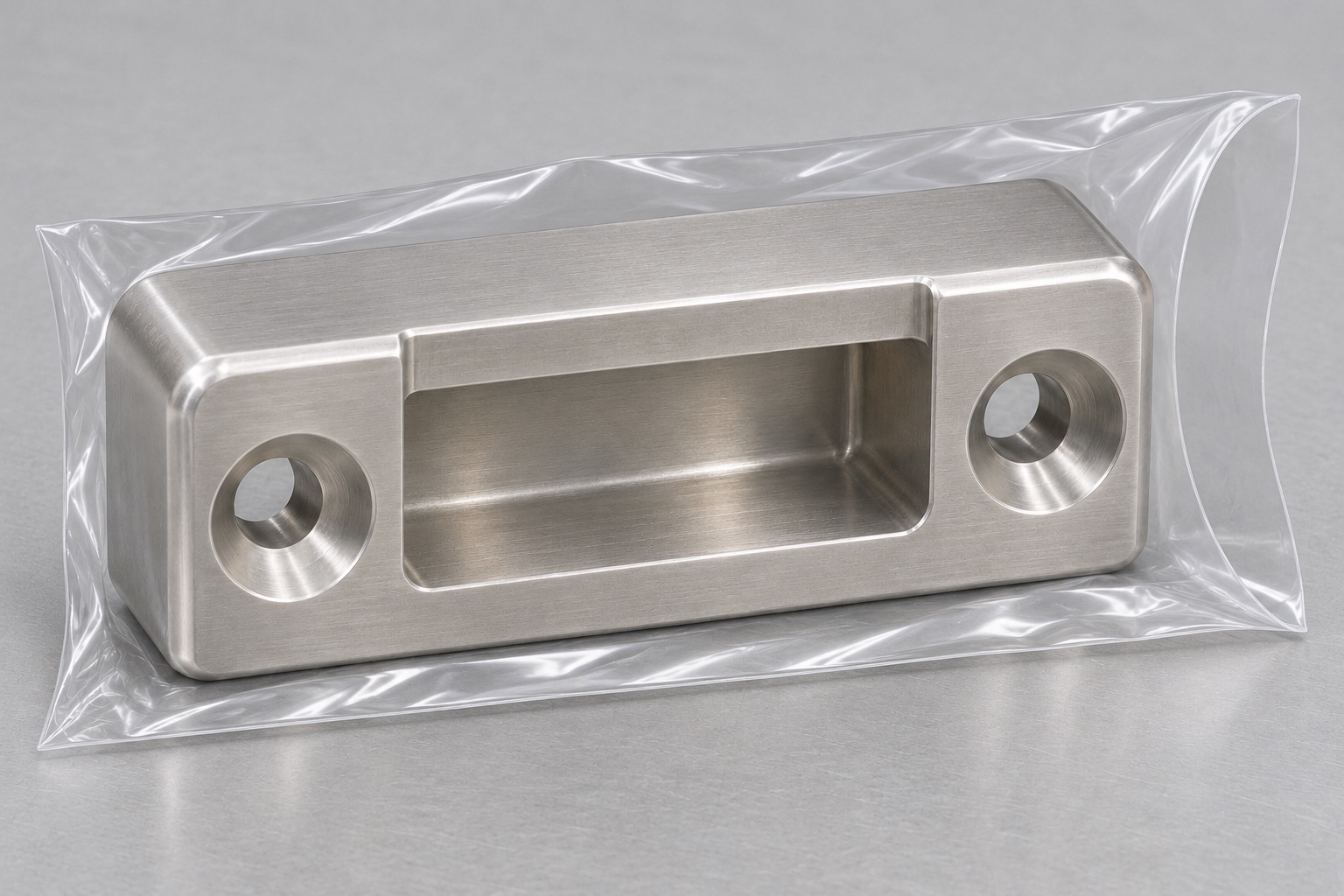
Pack each receiver in a recess that supports its rigid body without pressing on the lip. Keep loose screws and tongue samples separate so they cannot strike the pocket or rear face. Prevent hard-to-hard contact between blocks and link the outer label to the drawing revision, material lot and inspection report. This is ordinary transport protection, not a sterile barrier. At receipt, examine the pocket entrance, countersinks and rear face for handling marks. If an impact could affect seating or engagement, hold the part for the agreed dimensional checks before trying to force the latch into place.
FAQ
Can a tongue coupon replace pocket inspection?
It checks one fit condition. It does not establish pocket position to the mounting face, screw alignment or dimensions outside the coupon's contact region.
Why distinguish overlap from entry clearance?
A tongue can enter easily without reaching enough of the intended engagement surface. The design must define both closure access and the functional contact.
Does a flush screw prove a correct countersink?
No. Check the specified head form and seat. A mismatched angle may create limited contact even if the head does not protrude.
When should the pocket be measured?
Use the final accepted finish and drawing-defined support state. Measurements under heavy machining clamps may not represent the released part.
Does 316L establish cleaning compatibility?
No. Alloy choice is only one input. Define the chemical, handling and surface requirements through the equipment owner's approved process.
Does the bench latch trial prove retention strength?
No. The trial addresses geometric engagement and release in an unloaded fixture, not load capacity, transport durability or clinical suitability.

tanghangyun@oemach.com