
The core value of mill-turn is to put multiple rotary features, end faces and phase features into a shorter datum chain, but "one clamping" does not automatically eliminate spindle, clamping, thermal and tool errors.
The critical axes are closed in the same clamping and thermal state, the main and sub-spindle joints must be independently verified, and finally the functional coaxial relationship is confirmed by independent measurements. The specific process still needs to be combined with the functional axis, main and sub-spindle status, clamping deformation, splicing conversion, power tools, machine tool thermal status and independent testing and confirmation.
Typical problems, causes, controls and evidence
| Problem | Likely cause | Control action | Acceptance evidence |
|---|---|---|---|
| There is still runout after one clamping | The clamping datum itself is eccentric, thermal drift or turret geometric error | Verify fixture, spindle and live tool status and control thermal conditions | Spindle testing, on-machine probing and independent runout reporting |
| Axis changes after the main and auxiliary spindles receive materials | Material splicing synchronization, clamping force or main and sub-spindle alignment errors | Set up controlled splice surfaces and review functional features after conversion | Material splicing parameters, clamping marks, coaxial data before and after conversion |
| The position of the turning surface and the milled hole are inconsistent | There are errors in C-axis zero position, power tool or coordinate conversion | Check the rotation axis and tool coordinates, and independently inspect the first piece | Machine calibration, hole location, phase and CMM reporting |
Coaxiality problems often arise from datum conversion
In the traditional route, turning, milling, drilling and secondary turning are completed on different equipment, and each setup introduces alignment, fixture and temporary datum errors. Turn-milling combines more features into the same coordinate system, which can reduce cumulative errors and work-in-progress waiting. It is especially suitable for stepped shafts, eccentric holes, end holes and phase slot assemblies.
One-time clamping does not guarantee universal accuracy
Out-of-round chuck datums, thin walls deformed by clamping forces, thermal drift in the spindle, or geometric errors in the turret are all continually replicated in the same setup. The process should select a stable clamping section, control soft claw trimming, clamping force and extension, and complete key finishing after the machine tool reaches a stable thermal state.
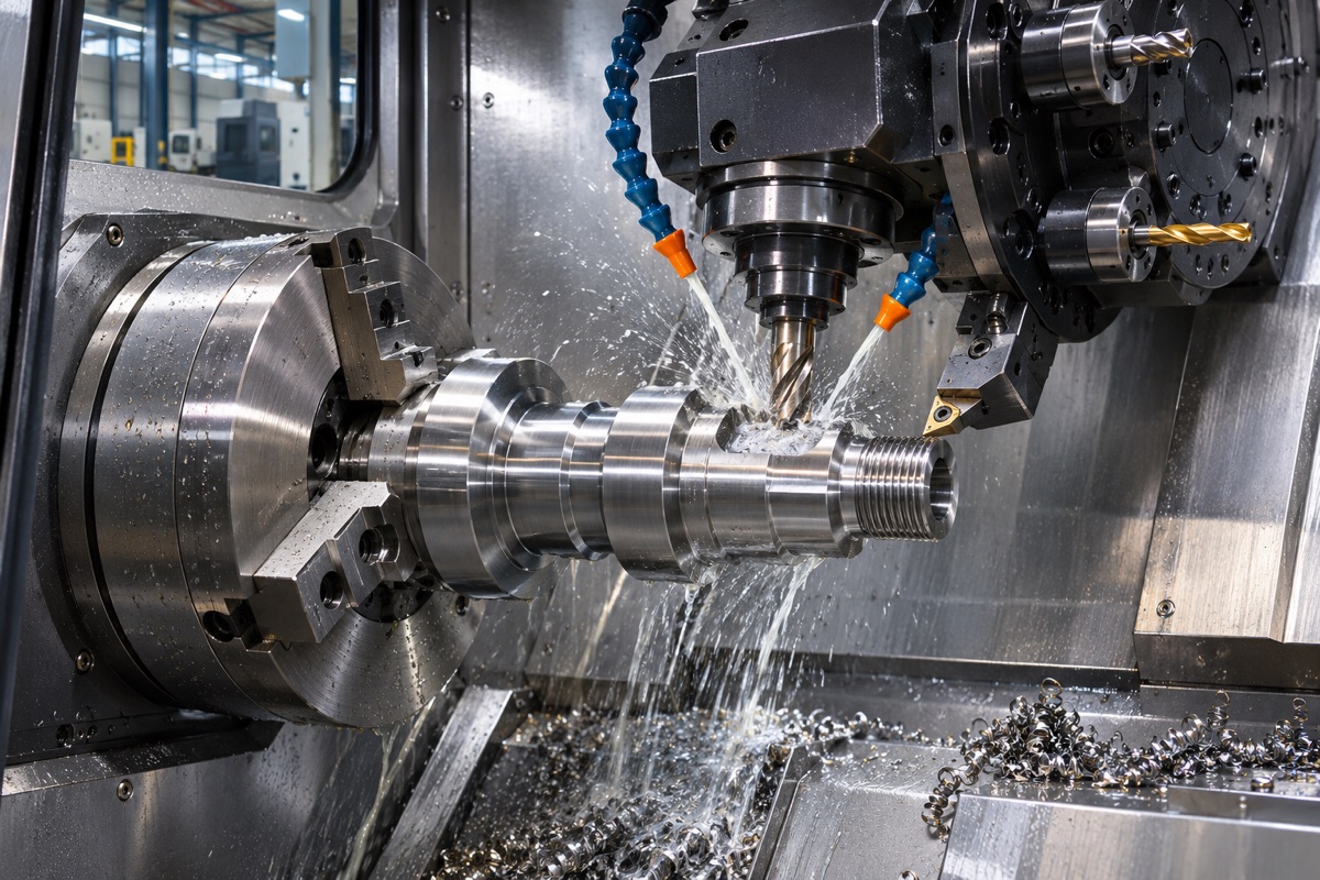
Centralizing the process can shorten the datum chain, but the clamping and machine tool status still need to be controlled.
Turning and milling features share functional axes
The outer circle, inner hole and end face should be established with the spindle rotation axis; the transverse hole, keyway and end hole processed by the power tool rely on the C-axis zero position, tool coordinates and rotation center. The phase and position of the first piece need to be verified, not just the turning runout. Program simulation should also include tool holder, chuck and material receiving actions.
The main and auxiliary spindle material connection is the second error chain
When parts are transferred to the sub-spindle, errors in main and sub-spindle alignment, synchronization, clamping surface cleaning, clamping force and splicing depth can occur. If critical coaxial features span machining before and after splicing, a controllable splicing datum should be arranged in the design and the runout, pinch marks, and dimensions before and after conversion should be compared.
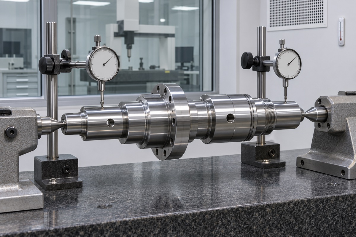
The final coaxial relationship should be independently tested against functional benchmarks.
Process concentration should also consider chip removal and tool life
Deep holes, internal grooves, and cross holes can allow chips to wrap around the finished surface; the rigidity of live tools is different from that of spindles, and the parameters cannot be copied from machining centers. Critical surfaces should be protected according to the machining sequence, chip breaking, cooling and tool changing rules should be set up so that coaxiality stability covers the entire batch and not just the first part.
Independent testing to confirm true returns
On-machine probes are suitable for alignment and trend monitoring, but share machine tool errors with cutting. OEMach recommends using a roundness meter, runout measuring tool or CMM for independent acceptance based on functional benchmarks, and comparing data between single machine complete processing and multi-machine routes to confirm whether turning-milling composites can truly improve the coaxial relationship and cycle time.
Summary
The critical axes are closed in the same clamping and thermal state, the main and sub-spindle joints must be independently verified, and finally the functional coaxial relationship is confirmed by independent measurements. The specific process still needs to be combined with the functional axis, main and sub-spindle status, clamping deformation, splicing conversion, power tools, machine tool thermal status and independent testing and confirmation.
FAQ
Can turning-milling composite completely eliminate secondary clamping?
Not guaranteed. Joining, heat treating, grinding or inaccessible features may still require subsequent clamping.
Can coaxiality be measured using a dial indicator only?
Dial indicators are suitable for runout inspection, but strict evaluation requires a combination of drawing definitions, datums, and applicable measurement methods.
The more concentrated the process, the shorter the delivery time will be?
Not necessarily. Complex programs, tooling and single-machine bottlenecks may also increase risks, requiring more complete cycles and waiting.
Ready to get a quote for your CNC machined parts?
Submit your engineering drawings to qiancj@oemach.com. We support prototype sampling and small-batch production with strict tolerance control.