
Installation of transmission parts does not mean stable operation. The tolerance fit must simultaneously consider the load direction, rotation speed, assembly and disassembly, temperature, lubrication, shape error and datum relationship.
The hole shaft tolerance zone, shape and surface requirements are deduced from the function and failure mode, and then the torque, temperature rise, noise and repeated positioning are verified through representative assembly. The specific process still needs to be confirmed based on the load, rotation speed, matching function, hole shaft reference, bearing and key connection, thermal status, lubrication and inspection rules.
Typical problems, causes, controls and evidence
| Problem | Likely cause | Control action | Acceptance evidence |
|---|---|---|---|
| The shaft hole size is acceptable but it gets hot during operation. | Form errors, surface, lubrication or thermal clearances are not included in the fit | Joint evaluation of size, roundness, roughness, temperature rise and lubrication | Bore shaft report, temperature rise, torque and running-in records |
| Key connections repeatedly loosen | Improper control of mating side, keyway position or load direction | Control and verify contact focusing on the work surface where torque is transmitted | Keyway Dimensional Position, Contact Mark and Load Test |
| Assembly batches behave discretely | Hole axis distribution superposition, material or measurement method fluctuations | Keep the measured matching data and analyze the matching distribution | Parts history, option records and operating trends |
First define what function is to be achieved by the cooperation
The same nominal diameter may be used for rotational support, precision positioning, sliding adjustment or permanent press-fitting, but the matching requirements are completely different. During the review, the load size and direction, rotation speed, operating temperature, maintenance frequency and allowable clearance or interference should be clarified, and then the basic hole or basic shaft system should be selected according to ISO 286 and other rules.
Dimensional tolerances cannot replace shape and position
If the bore diameter falls within the range but there is an ellipse, taper, or axis offset, the bearing may still be stressed unevenly. The roundness, cylindricity, runout and verticality of the journal, bearing hole, positioning end face and coupling hole must be controlled around the functional benchmark, and key coaxial features should be finished in the same clamping and hot state as much as possible.
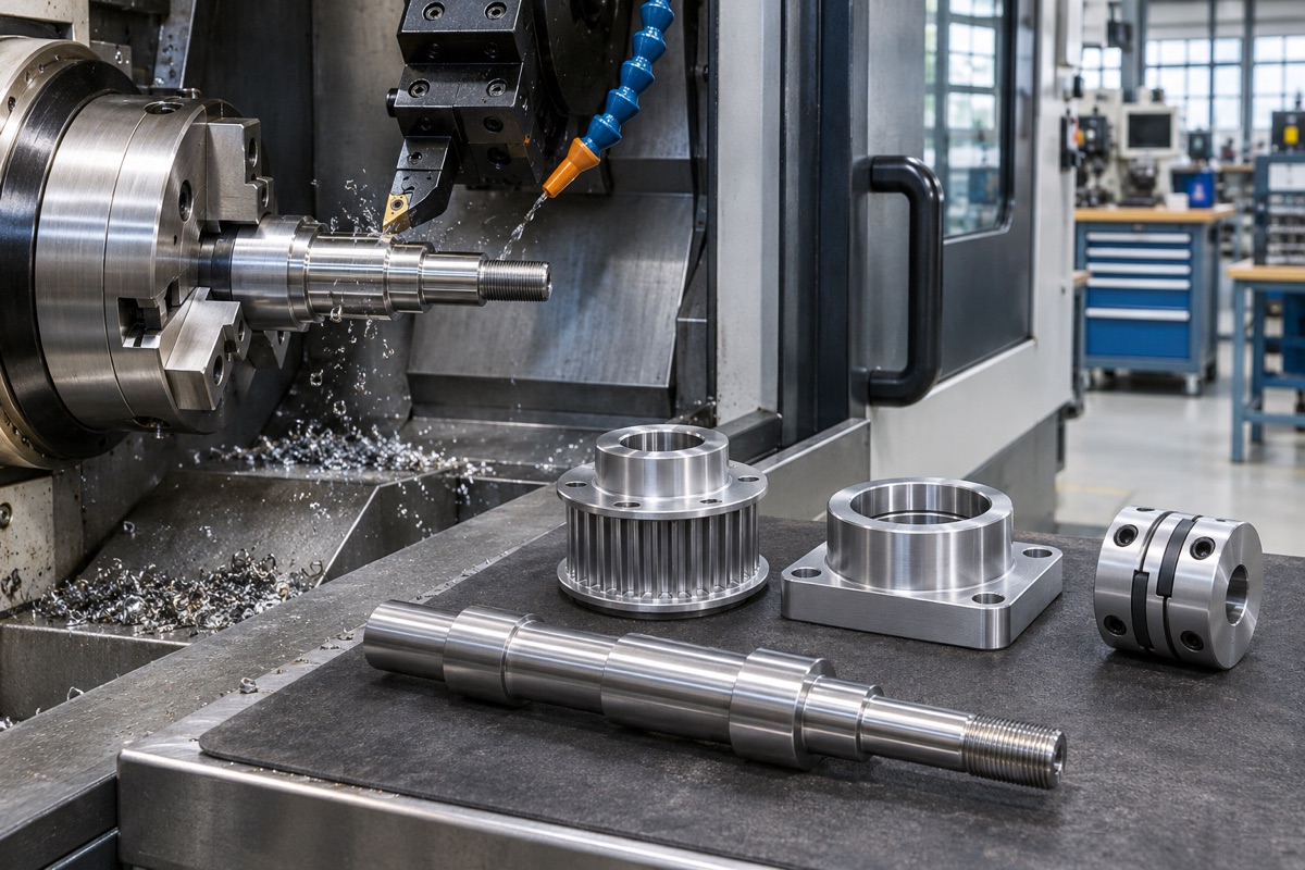
Transmission parts should be planned and processed uniformly around the functional axis.
Bearing position should be combined with clearance and load circle
Which of the inner and outer rings of the bearing rotates with the load will affect whether a tighter fit is required. If it is too loose, the climbing ring may be worn, and if it is too tight, the internal clearance will be reduced and the temperature rise will increase. The correct solution is also affected by the shell material, wall thickness, temperature difference and assembly method, and cannot be copied directly from a general table.
Keys, splines and couplings depend on the working surface
Key connections transmit torque primarily sideways, and the top of the key should generally not be a point of false interference. Keyway width, depth, symmetry and relative axis position are jointly evaluated. For clamping couplings, it is also necessary to confirm the relationship between the opening, thread and clamping cylinder to avoid pulling the shaft off after tightening.
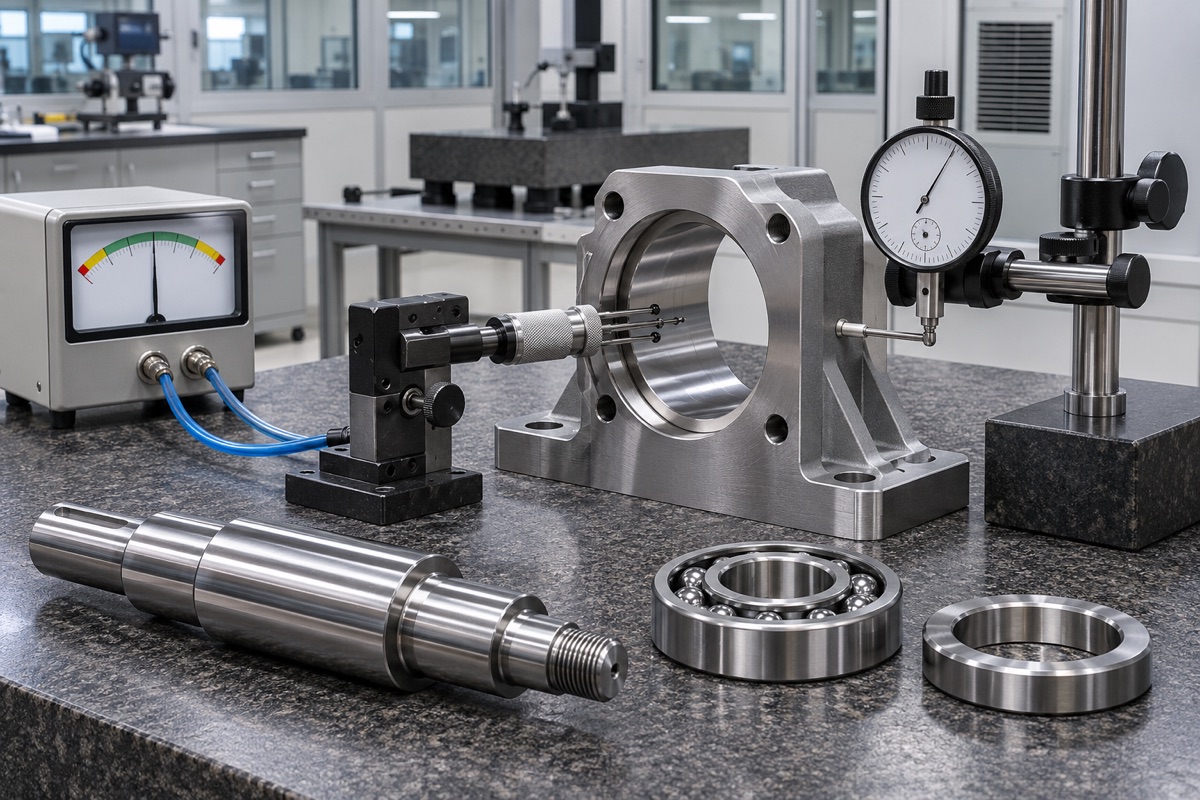
Cooperation acceptance should cover size, shape, surface and assembly function.
Surfaces and assembly processes can alter the actual fit
Roughness peaks, burrs, coatings, anode layers, cleaning residues and press temperature differences all affect actual contact. Drawings should illustrate final condition dimensions and treatment masking. Use controlled heating, cooling or pressing force during assembly, record abnormal curves, and do not use impact assembly to cover up fit problems.
Relate part data to run results
OEMach recommends retaining the actual measured values of the shaft hole, matching relationship, pressing force or starting torque in the first batch, and corresponding to the temperature rise, noise and repeated positioning. Only in this way can we subsequently determine whether the problem comes from tolerance allocation, machining drift, or assembly and lubrication.
Summary
The hole shaft tolerance zone, shape and surface requirements are deduced from the function and failure mode, and then the torque, temperature rise, noise and repeated positioning are verified through representative assembly. The specific process still needs to be confirmed based on the load, rotation speed, matching function, hole shaft reference, bearing and key connection, thermal state, lubrication and inspection rules.
FAQ
Is H7/g6 suitable for all rotating axes?
Not suitable. The fit should be selected according to the size segment, load, speed, temperature, material and assembly and disassembly requirements.
Is it enough to measure the bearing hole in only two directions?
Usually not enough. High-demand bearing locations should also pay attention to multiple cross-sections, roundness, cylindricity and axis relationships.
The larger the interference, the more reliable the positioning is.
No. Excessive size may damage parts, reduce bearing clearance and increase temperature rise.
Ready to get a quote for your CNC machined parts?
Submit your engineering drawings to qiancj@oemach.com. We support prototype sampling and small-batch production with strict tolerance control.