
The accuracy target of lens barrels and frames is not an isolated aperture value, but the relationship between the optical axis of the lens, the mechanical mounting datum and the assembly preload. Micron-scale representations must correspond to specific features, conditions, and measurement uncertainties.
First establish a reproducible optical-mechanical benchmark, and then control the lens holder, stop, thread and external interface; processing, cleaning, assembly and optical verification should form the same chain of evidence. The specific process still needs to be confirmed by combining the optical axis, mechanical reference, lens holder, stop face, thread, locking preload, temperature and measurement uncertainty.
Typical problems, causes, controls and evidence
| Problem | Likely cause | Control action | Acceptance evidence |
|---|---|---|---|
| The optical axis shifts after the lens is installed | The lens holder, stop surface and external installation datum do not form a unified axis system | Close key inner holes and end faces at one time based on functional standards, and review eccentricity and inclination after assembly | Baseline plan, circular runout, end face verticality and assembly centering data |
| The threads are acceptable but the lens group is tilted | The thread axis is not axial with the lens holder or the locking preload is uneven | Control the thread relative to the functional axis and verify the locking sequence and torque | Thread gauge, axis relationship, and retest records before and after locking |
| Qualified at room temperature but temperature drift during use | Thermal expansion of lens, lens barrel and adhesive layer does not match | Establish temperature error budget and preserve radial and axial compensation space | Material coefficient, temperature cycle and optical-mechanical retest results |
First convert the optical axis into a machinable mechanical datum
The optical axis of the lens itself cannot be directly identified by the turning tool. The design needs to establish a mechanical datum using the lens holder cylindrical surface, stop end surface, positioning stop or external mounting surface, and explain how these features represent the optical axis. If different lens mounts are aligned separately, even if their respective apertures are qualified, the lens assembly may still be eccentric and tilted.
Micron level must fall into characterization and error budget
"Ultra-high precision" cannot just be written as a unified ± value. Lens holder diameter, roundness, cylindricity, end face perpendicularity, thread axis and mounting interface have different effects on imaging and should be assigned by optical tolerance analysis. Gage resolution is also not equal to measurement uncertainty, and temperature, clamping, fit, and repeatability are evaluated near specification boundaries.
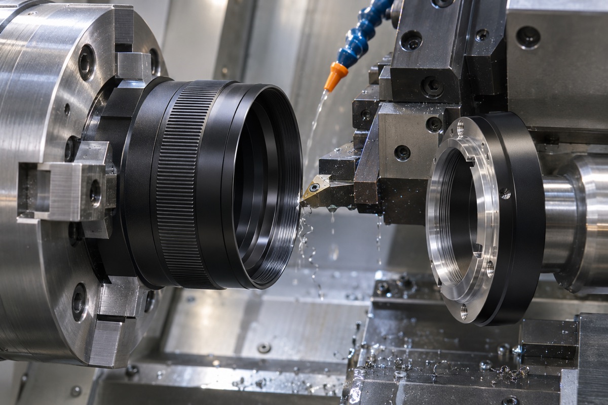
Key lens mounts, tabs and threads should be machined around a unified functional axis.
One datum closure takes precedence over multiple alignments
The rotationally symmetrical lens barrel can prioritize the finishing of key inner holes, stop faces and reference outer circles in the same clamping, reducing datum conversion. When facing or milling interfaces is required, completed functional datum positioning should be used and repeat alignment verified. The thin-walled lens barrel must also limit the clamping force of the chuck to avoid deformation after the clamping state is qualified and the clamp is released.
Precision threads and locking structures also change the optical axis
It is not enough to pass the pass and stop specifications for the pressure ring thread. If the thread is eccentric relative to the lens holder, the end face is not vertical, or the pressure ring contacts unevenly, it may cause the lens to tilt due to force. The thread axis, pressure ring end face, contact position and locking sequence should be controlled, and if necessary, the eccentricity, inclination or wave front changes before and after locking should be recorded.
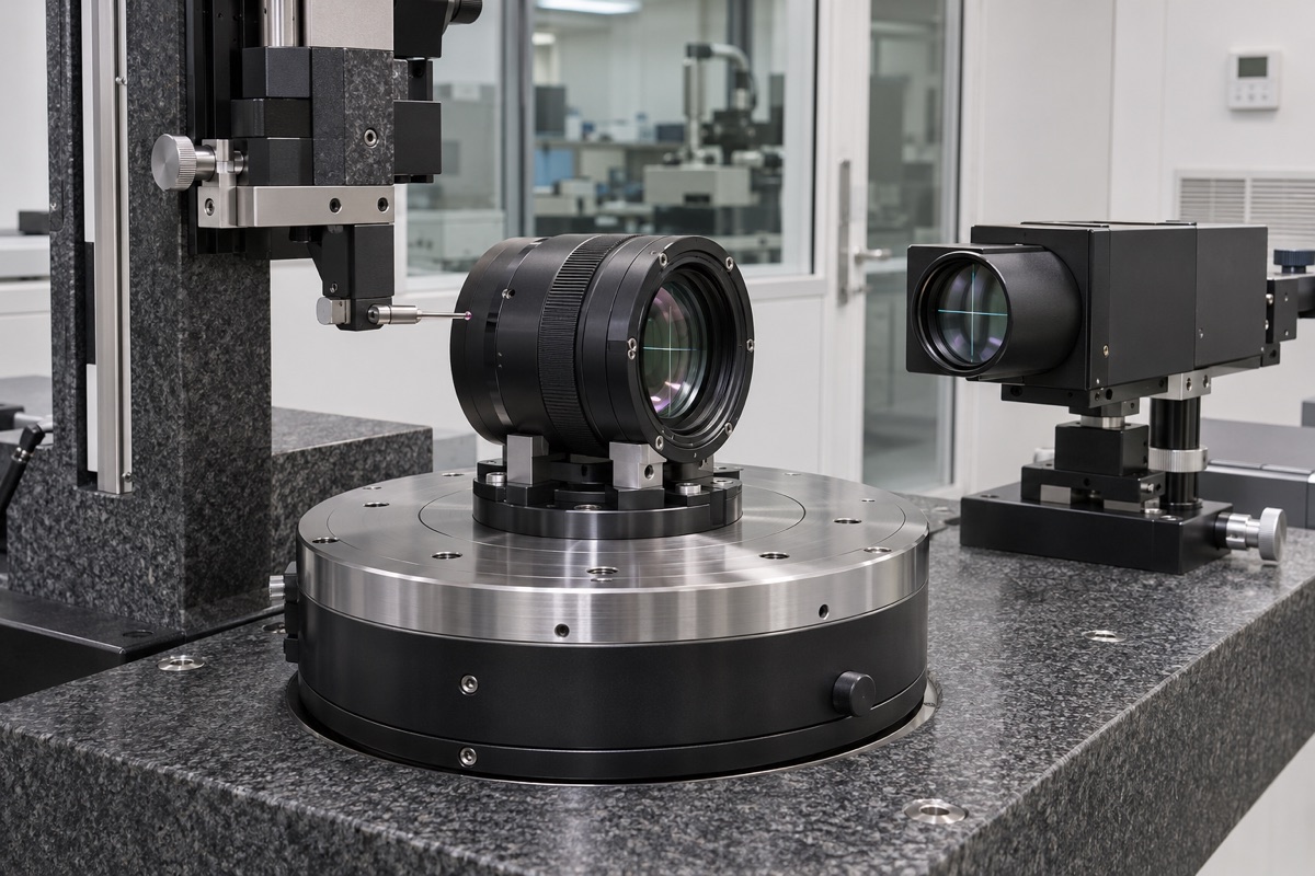
Micron-level conclusions require clear measurement status, methods and uncertainties.
Materials, surfaces and cleaning influence long-term stability
Aluminum alloys, stainless steel, lenses and adhesive layers have different thermal expansions, and temperature changes may change the gap and preload. The black finish also changes the dimensions and contact conditions. After processing, the optical contact area should be deburred, cleaned and protected to avoid accumulation of particles or anode layers becoming a source of assembly tilt.
Processing inspection and optical verification should be related
Roundness gauge, CMM and runout measurements are used to verify mechanical characteristics, and post-assembly eccentricity, tilt or imaging testing is used to verify system functionality. OEMach (OEMach) recommends that the actual measured value of the part should be matched with the assembly result to determine whether the error comes from processing, lens, locking or temperature.
Summary
First establish a reproducible optical-mechanical benchmark, and then control the lens holder, stop, thread and external interface; processing, cleaning, assembly and optical verification should form the same chain of evidence. The specific process still needs to be confirmed by combining the optical axis, mechanical reference, lens holder, stop face, thread, locking preload, temperature and measurement uncertainty.
FAQ
Is the micron level equal to ±0.001mm for all dimensions?
No. Critical features and error budgets should be determined by the optical function, and excessive tightening of non-critical dimensions will increase cost and cycle time.
Can the lens holder be inspected using only the inner diameter gauge?
Bore gauges can check dimensional trends, but roundness, cylindricity, axis and face relationships require matching shape or coordinate measurements.
Is it necessary to retest after black anodizing?
Needed. Coatings and masking may alter fits and faces, and critical dimensions and fit should be verified in final condition.
Ready to get a quote for your CNC machined parts?
Submit your engineering drawings to qiancj@oemach.com. We support prototype sampling and small-batch production with strict tolerance control.