
Ra0.4 or Ra0.8 is a measurement result, not a processing label determined only by the feed formula. Different materials, surface orientations, filtering and functional requirements will change the process and acceptance conclusions.
First define the surface texture and measurement specifications, then control tool runout, effective cutting edge, feed, stepover, machine tool thermal state and chip evacuation; prove that "direct milling" is stable and feasible through first part and process data across tool life. The specific process still needs to be combined with functional surfaces, Ra definition, sampling direction and filtering, tool runout, feed texture, machine tool thermal state, burrs and measurement consistency confirmation.
Typical problems, causes, controls and evidence
| Problem | Likely cause | Control action | Acceptance evidence |
|---|---|---|---|
| Ra reading is acceptable but sealing or sliding performance is poor | Ra cannot describe directionality, ripples, peaks and valleys, and defects | Simultaneously specify grain direction, contour or functional parameters and appearance defects | Measuring conditions, profile curves, functional tests and appearance records |
| Different directions on the same surface give different results | The stylus direction is inconsistent with the processing texture, sampling length or filtering | Fixed measurement direction and specification operators in drawings and inspection procedures | Instrument status, orientation, filtering, evaluation length and repeat data |
| Ra0.4 for the first article but gradually getting worse in batches | Tool runout, wear, thermal drift or chip scoring | Control tool status, runout and thermal conditions and use trends to determine tool changes | Runout, roughness trends, wear and surface photos |
First write the complete requirements of Ra
ISO 21920-2 defines the surface texture parameters of the contour method, and ISO 21920-3 specifies the specification operator. In addition to the Ra value, the drawings should also clearly indicate the applicable surface, texture direction, measurement direction, filtering or nesting index and evaluation length. If measured along the knife pattern and across the knife pattern, the results may be significantly different; just writing "Smoothness Ra0.4" may easily lead to acceptance disputes.
Ra cannot describe all functional risks
Ra is the arithmetic mean parameter of the profile and cannot alone express ripples, single deep scratches, peak and valley morphology, directionality or sealing paths. Sealing surfaces, sliding surfaces, optical mounting surfaces and appearance surfaces may also require contour, flatness, grain direction, defect limits and functional testing. The prerequisite for eliminating the need for polishing is that the milling results meet these functional requirements.
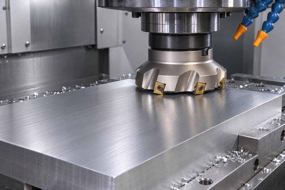
Tool runout, effective edge and stable feed determine surface texture.
Tool runout allows part of the edge to do all the finishing
If the axial runout of a face mill or multi-edge tool is large, the highest blade will dominate the surface, and its wear will quickly change the roughness. The spindle, tool holder, tool body and insert seat should be checked for cleanliness, the repeatability of tool installation should be controlled, and suitable finishing inserts and cutting methods should be used. Tool extension, machine tool vibration, and workpiece support can also create periodic textures.
Feed, step and attitude work together to generate the surface
Sandvik data points out that feed, depth of cut, tool runout and tool inclination all affect curved and contour milled surfaces. Reducing the feed or step length can usually reduce the theoretical tool pattern, but too small a cutting thickness can become friction and accelerate chip accumulation. The stable window should be found within the allowable range of the material, tool and machine tool, rather than infinitely reducing parameters.
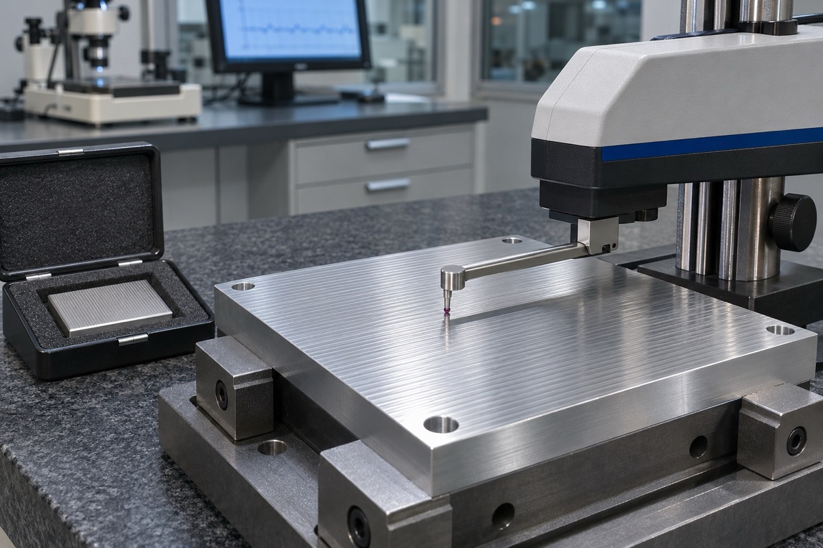
Ra results must be bound to direction, filtering, evaluation length and instrument status.
Thermal conditions and chip removal determine batch stability
It is easy to get better readings when the first piece is cold, the tool is new and the surface is clean. Thermal drift, wear and secondary chip scratches in the batch will change the results. Preheating, tool life, cooling and cleaning methods should be specified and tested at the first, middle and end of life. Chips and oil films must be removed before measurement, and the results cannot be changed by manual polishing.
The title is a conditional method, not an unconditional promise
"No need for secondary polishing" is only true for proven materials, structures, tools, machine tools and functional surfaces. OEMach (OEMach) recommends using a representative surface for test cutting, saving parameters, runout, roughness profile and appearance evidence before deciding whether to cancel polishing; it cannot promise Ra0.4 for any part without verification.
Summary
First define the surface texture and measurement specifications, then control tool runout, effective cutting edge, feed, stepover, machine tool thermal state and chip evacuation; prove that "direct milling" is stable and feasible through first part and process data across tool life. The specific process still needs to be combined with functional surfaces, Ra definition, sampling direction and filtering, tool runout, feed texture, machine tool thermal state, burrs and measurement consistency confirmation.
FAQ
Is Ra0.4 definitely better than Ra0.8?
Not necessarily. Function, cost and other surface parameters should be considered. Excessive tightening will increase the difficulty of manufacturing and measurement.
Can all post-processing be omitted after direct milling reaches Ra0.4?
It cannot be generalized. Also look at deburring, cleaning, corrosion resistance, sealing and appearance requirements.
Can one reading of the roughness meter be used as a batch conclusion?
No. Measurements should be repeated in the specified direction and conditions, and tool life and batch trends should be observed.
Ready to get a quote for your CNC machined parts?
Submit your engineering drawings to qiancj@oemach.com. We support prototype sampling and small-batch production with strict tolerance control.