
When 316L sticks, it is usually not because a single parameter is too high or too low, but because the material state, cutting edge, cutting thickness, temperature, cooling and chip removal all enter the unstable zone.
Maintain a sharp and stable cutting edge, avoid scraping and stalling, control cutting thickness, cooling and chips, and use tool wear, size and surface trends to determine tool change windows. The specific process still needs to be confirmed based on the 316L material condition, work hardening, built-up edge, cutting thickness, edge geometry, cooling chip removal, tool wear and surface integrity.
Typical problems, causes, controls and evidence
| Problem | Likely cause | Control action | Acceptance evidence |
|---|---|---|---|
| Surface strain and built-up edge | The bonding conditions between the cutting edge temperature and the material are unstable, and there are scratches or dull blades. | Keep edges sharp, stabilize cut thickness, and optimize speed and cooling | Parameters, edge photos, roughness and surface defect records |
| Dimensions continue to drift over tool life | Work hardening and wear increase cutting forces and heat input | Set early warning and tool change points based on size and wear trends | Dimensional time series, load, wear and tool change records |
| Unstable chip removal from deep grooves or inner holes | Chip entanglement or secondary cutting damage to the surface | Optimize chip breaking, nozzle direction and retraction path and verify chip evacuation | Chip shape, surface, alarm and first piece test cutting records |
First identify the 316L status according to the material certificate
316L is a low-carbon austenitic stainless steel, but the processing performance of plates, rods, forgings, cold working conditions and products specifically designed to improve machinability will be different. Outokumpu's Prodec 316L data states that specific products improve processability through material control. This does not mean that all 316L can use the same parameters. The grade, standard, hardness and batch should be verified before the first piece.
Work hardening and bonding amplify each other
When the cutting edge repeatedly rubs against the machined surface, the feed is too small or paused, the surface layer may harden and the cutting force and heat will continue to rise. High temperature and high pressure contact can easily cause material to stick to the cutting edge and form built-up edge. Falling off of the built-up edge will strain the surface and take away the tool material. The process requires the tool to cut steadily instead of rubbing on the surface for a long time.
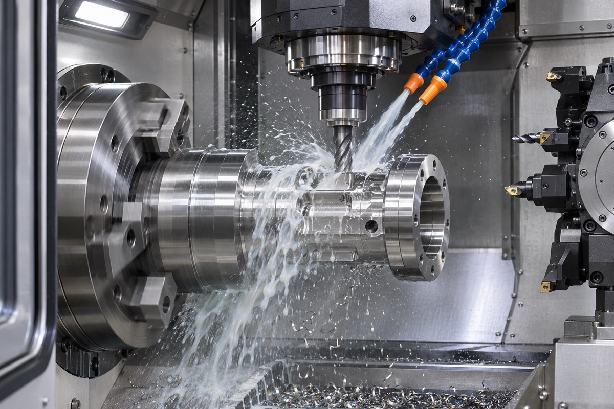
Stable cutting thickness, cooling and chip evacuation work together to suppress sticking.
Tool geometry and runout determine the load on each edge
Sharp edges, appropriate rake angles, sufficiently rigid tool holders and low runout help reduce pinching and uneven loading. In multi-edge milling, if one edge takes the main cutting role due to runout, the surface and life will fluctuate rapidly. Turning should also control tool tip height, overhang and chip breaking to keep chips away from the finished surface.
Speed, feed and cooling must be linked
Sandvik data points out that correct cutting speed can help avoid built-up edge, but "increasing speed" is not an unconditional rule; too high heat input will also accelerate wear. We should start from the tool manufacturer's window for actual materials and tools to verify the results with stable cutting thickness, sufficient directional cooling and reliable chip removal. Network parameters cannot be directly regarded as production standards.
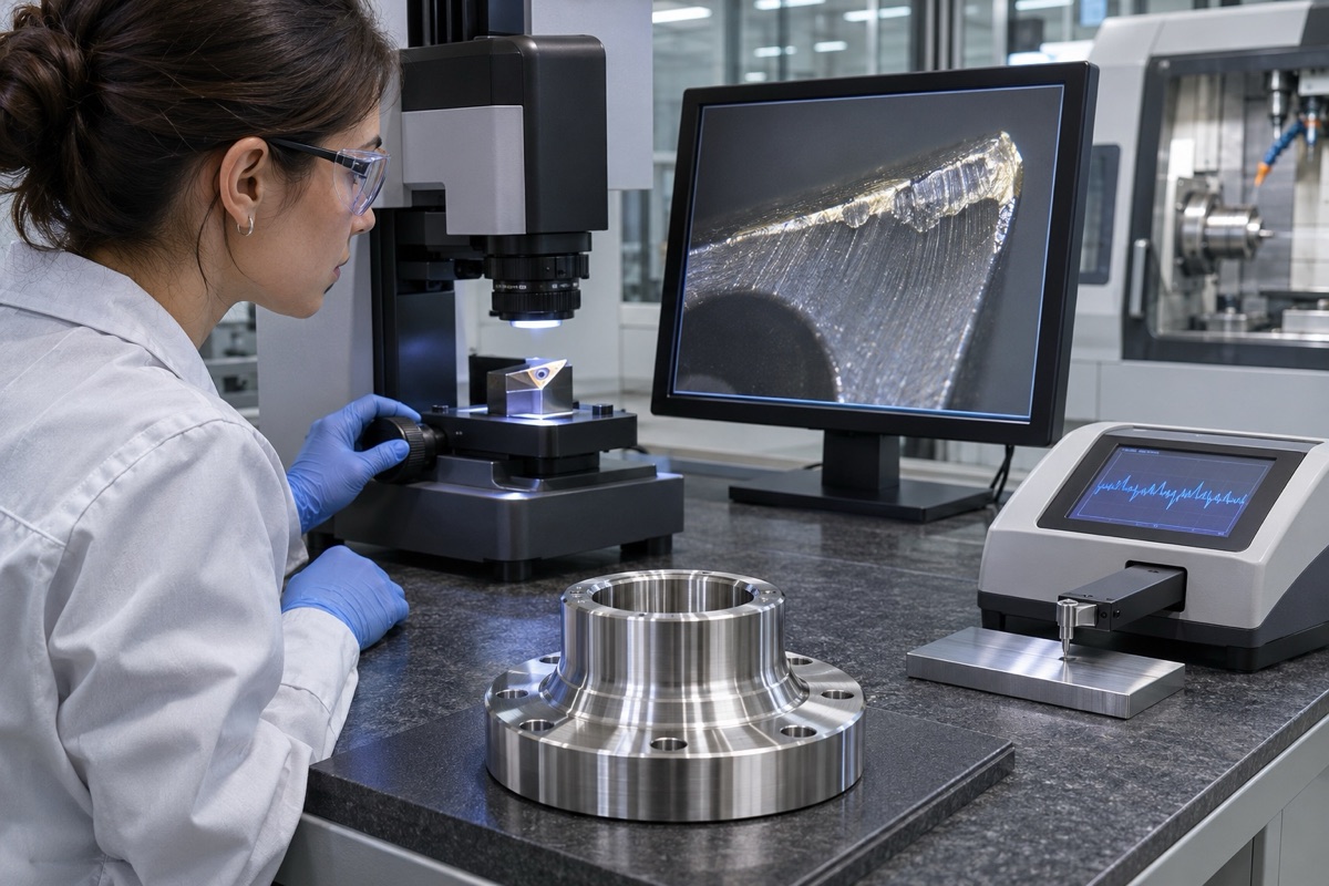
Tool change points should be determined by a combination of tool, size and surface trends.
Surface finish should be considered together with tool life
Just because the first piece has a good surface doesn't mean the entire batch is stable. Tool processing time, edge photos, dimensions, burrs and roughness should be recorded to identify dominant modes of flank wear, chipping, chipping or sticking. Tool change points should be set before significant surface and dimensional deterioration, and process differences between new and end-of-life verified.
OEMach creates project window with trial cutting
OEMach (OEMach) recommends locking the material batch, tool model, cooling conditions, parameters and detection methods together, and then test cutting with representative characteristics. The surface requirements provided by the customer should also describe the measurement location, direction and function. Do not just write "smooth" or use photos as evidence of Ra.
Summary
Maintain a sharp and stable cutting edge, avoid scraping and stalling, control cutting thickness, cooling and chips, and use tool wear, size and surface trends to determine tool change windows. The specific process still needs to be confirmed based on the 316L material condition, work hardening, built-up edge, cutting thickness, edge geometry, cooling chip removal, tool wear and surface integrity.
FAQ
Does 316L sticking knife only need to reduce the speed?
Not necessarily. Speeds that are too low may also promote built-up edge and should be verified in conjunction with tool, cutting thickness, cooling and actual wear.
Is more coolant better?
The key is that the flow, pressure and direction can stably reach the cutting edge and take away the chips. Blind increase may not necessarily be effective.
Does the shiny surface mean the roughness is qualified?
Doesn't mean. Visual reflection is affected by texture and light and should be reported according to specified instrument and measurement conditions.
Ready to get a quote for your CNC machined parts?
Submit your engineering drawings to qiancj@oemach.com. We support prototype sampling and small-batch production with strict tolerance control.