
One-time clamping can reduce datum conversion, but it cannot automatically guarantee coaxiality. The results still depend on whether the functional reference is correct, whether the tool and turntable movements are reliable, and whether the hole system has a unified machining and measurement definition.
The key holes and end faces should be planned around the same functional datum, and should be completed in the same clamping, the same thermal state and the same coordinate system as much as possible; the final acceptance should be based on the common axis, direction and measurement strategy defined in the drawing. The specific process still needs to be combined with functional datums, common axes, accessibility to one clamping, tool deflection, hole system machining sequence, datum alignment and task-specific measurement uncertainty confirmation.
Typical problems, causes, controls and evidence
| Problem | Likely cause | Control action | Acceptance evidence |
|---|---|---|---|
| Each hole is individually qualified but the common axis is out of tolerance | Holes are fitted separately or different machining and inspection datums are used | Establish common axes and unify machining and measuring strategies based on functional benchmarks | Datum sequence, hole axis fit, origin points and comprehensive reporting |
| After one clamping, the hole still has a large opening and a small bottom. | Long tool deflection, chip removal, temperature rise or uneven allowance cause taper | Control tool extension and uniform allowance, stage finishing and multi-section inspection | Bore section, cylindricity, tool status and temperature logging |
| The coaxiality is good but the verticality of the end face is not up to standard. | The end face and hole system are not processed around the same functional datum | The key end faces and holes are completed in the same datum chain and jointly accepted. | End face orientation, hole axis relationship and datum reproduction record |
First distinguish the size, location and orientation requirements
Qualified aperture does not mean that the holes are coaxial, nor does it mean that the end face is perpendicular to the axis. Drawing review should confirm the datum features, datum sequence, definition of common axis or independent axis of each hole, and objects on which verticality acts. The ISO GPS system expresses datum, dimensions and geometric tolerances separately, and both process and inspection must be executed according to the same semantics.
The value of one clamping is to shorten the reference chain
If multiple key holes, positioning end faces and mounting surfaces can be completed in the same clamping, the accumulated errors caused by overturning, repeated positioning of the fixture and temporary benchmarks can be reduced. One-time clamping does not mean that it is never loosened from the blank to the finished product, but that the key finishing features are closed in a stable functional datum and the same coordinate system. Rough machining can still release stress in stages.
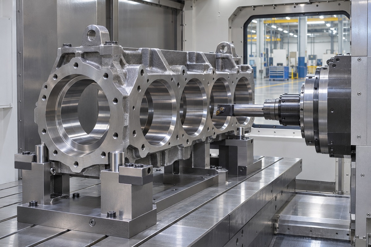
The core of one-time clamping is to make the key hole and the end face share a stable benchmark.
Tooling should take into account positioning, clamping and tool accessibility
The positioning points should fall in rigid and functionally relevant areas, and the clamping force should not deform the box or thin-walled hole seat. Lateral boring, deep holes and cross holes require reserved space for tool holders, probes and chip removal. If the attitude of the turntable changes greatly, the direction of gravity and the stiffness of the fixture must be checked to avoid small changes in the position of the parts at different angles.
Hole finishing requires control of deflection and thermal state
First establish a stable reference hole or end face, and then complete the key hole with a uniform margin. Long boring bars, extended tool extensions, and discontinuous cuts can amplify deflection; tool wear and machine tool thermal drift can also create hole diameter and axis trends. Extrusion should be limited, cooling chip evacuation should be stable, and the size and shape of the inlet, middle, and outlet should be checked on representative holes.
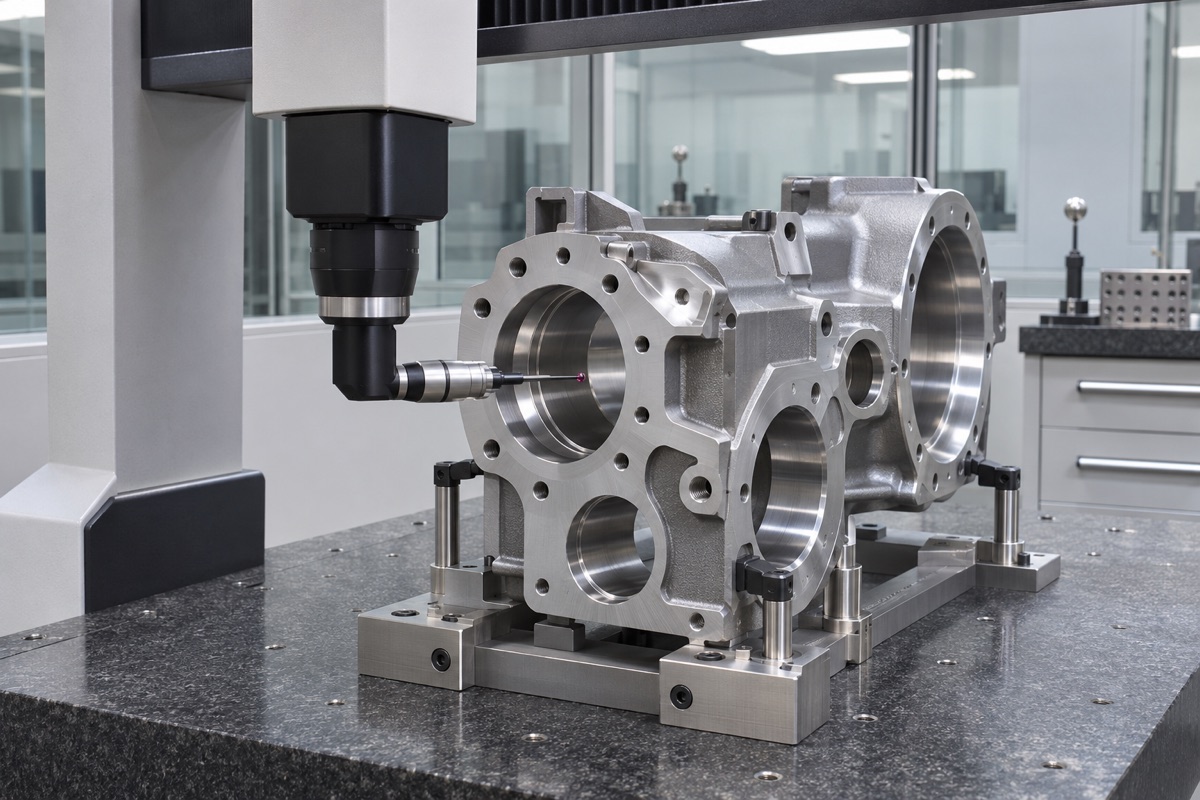
Machining and measurement must use consistent datum and feature definitions.
On-machine detection is used for alignment, and independent testing is used for acceptance.
The on-machine probe is suitable for establishing workpiece coordinates, confirming margins and monitoring trends, but the probe and cutting share the machine tool error chain and cannot automatically replace independent CMM acceptance. Final inspections should be aligned to drawing datums, specifying acquisition points, cylinder fits, common axis algorithms, and end face orientations, and accounting for task-specific measurement uncertainties near boundaries.
When one-time clamping is not possible, the conversion must be turned into a verifiable process
Part size, equipment travel, or accessibility may force flipping. At this time, the processed and stable functional datum should be used to reproduce the coordinates through positioning pins, datum planes and on-machine detection, and correlation verification should be done on the common features before and after conversion. OEMach will review datum conversion, tooling repeatability and final hole pattern reports as the same first package.
Summary
The key holes and end faces should be planned around the same functional datum, and should be completed in the same clamping, the same thermal state and the same coordinate system as much as possible; the final acceptance should be based on the common axis, direction and measurement strategy defined in the drawing. The specific process still needs to be combined with functional datums, common axes, accessibility to one clamping, tool deflection, hole system machining sequence, datum alignment and task-specific measurement uncertainty confirmation.
FAQ
Is one clamping definitely better than two clampings?
Not necessarily. If the tool accessibility or tooling stiffness is insufficient, forcing one-time clamping may increase the risk of deflection and collision. The selection should be based on the error budget and verification results.
Can coaxiality be checked using only the mandrel?
Mandrels are suitable for quick assembly checks but are not a complete replacement for geometric measurements that require datums, common axes and uncertainties.
Is the more CMM points collected, the more accurate it is?
Not necessarily. The sampling point distribution, feature shape, probe, algorithm and temperature will all affect the results and should be designed according to the measurement task.
Ready to get a quote for your CNC machined parts?
Submit your engineering drawings to qiancj@oemach.com. We support prototype sampling and small-batch production with strict tolerance control.