
The risk of thin-walled cavities does not only occur at the cutting moment, but the stress of the blank, the removal sequence, the clamping method and the measurement state jointly change the shape of the part. Vacuum suction cups should only be used if the suction area, sealing and cutting load have been verified.
First define the free state and functional benchmark, and then verify the vacuum plan based on the effective adsorption area; only by adopting low-stress clamping, symmetrical layered removal, coarse and fine separation, and loose clamping and retesting can the results of thin walls less than 1mm be stabilized. The specific process still needs to be confirmed by combining the thin-wall free state, blank residual stress, vacuum effective area, sealing partition, cutting load, rough and fine separation and loose clamp retest.
Typical problems, causes, controls and evidence
| Problem | Likely cause | Control action | Acceptance evidence |
|---|---|---|---|
| The cavity opens or warps after loosening the tooling | Blank residual stress, asymmetric removal and clamping pre-deformation superposition | Symmetrically remove materials in layers, release after rough machining and retest in free state | Blank certificate, outline of each stage, clamping status and unclamping data |
| Vacuum adsorption becomes unstable midway | Insufficient effective adsorption area, seal leakage or cutting load exceeding margin | Calculate and seal according to the effective area, set up vacuum monitoring and pressure loss shutdown | Vacuum settings, leak checks, test cutting loads and alarm verification |
| Thin wall dimensions change during measurement | Inconsistent support, force measurement, temperature, or stabilization time | Agree on the free state and support points, and use low force or non-contact review | Measurement status, environment, repeatability and final inspection report |
After less than 1mm, the part shape depends on the state
The thin-walled cavity still has overall stiffness in the blank stage. After the material is removed, the wall plate will become sensitive to clamping force, cutting force, temperature difference and residual stress. Drawings should illustrate the free state, specify the supported or assembled state, and identify which wall thicknesses, planes, and hole locations have functional significance. If clamps are used to force flattening during inspection, even if the report is qualified, it may rebound during assembly or storage.
Stress relief relies on staged data
The so-called "stress relief" does not mean adding a long-term placement process. First, the risk must be judged from the material status, blank direction and removal ratio, and then rough machining in a symmetrical, layered, and alternating area manner. After most of the material has been removed, the clamping should be released, cleaned and retested at controlled temperature, with semi-finishing and finishing allowances reallocated based on true deformation.
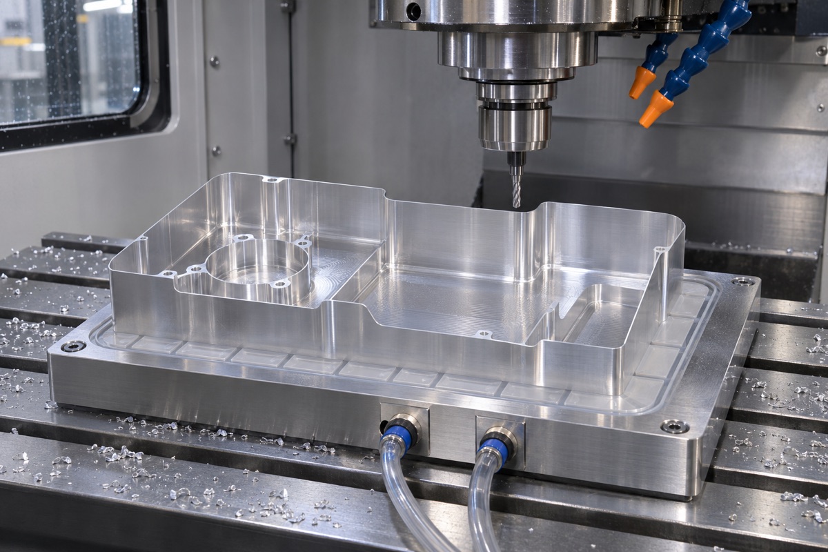
Vacuum clamping requires calculation of effective area, sealing and cutting load.
The vacuum suction cup is suitable for flat surfaces, but it is not a universal tool
Vacuum clamping can distribute the load to a larger area and reduce the indentation and bending caused by point-like mechanical clamping. It is suitable for thin-walled flat plates or cavities with continuous sealing surfaces. The available clamping force depends on the effective area, pressure differential, friction and safety factor; holes, grooves, cast surfaces or leakage channels will reduce the effective area. Insufficient vacuum must be monitored and a safety shutdown triggered.
Sealing partitions and cutting directions should be designed together
Tooling should combine the area to be processed, the sealing ring and the vacuum zone to prevent the tool from cutting off the sealing path. The direction of the cutting force should try to make the part press against the support instead of lifting it from the suction cup. The auxiliary connection or process table can be retained during rough machining, and then removed after the overall stiffness and benchmark are stable; a smaller, continuous cutting load is used in the final stage to reduce wall plate vibration.
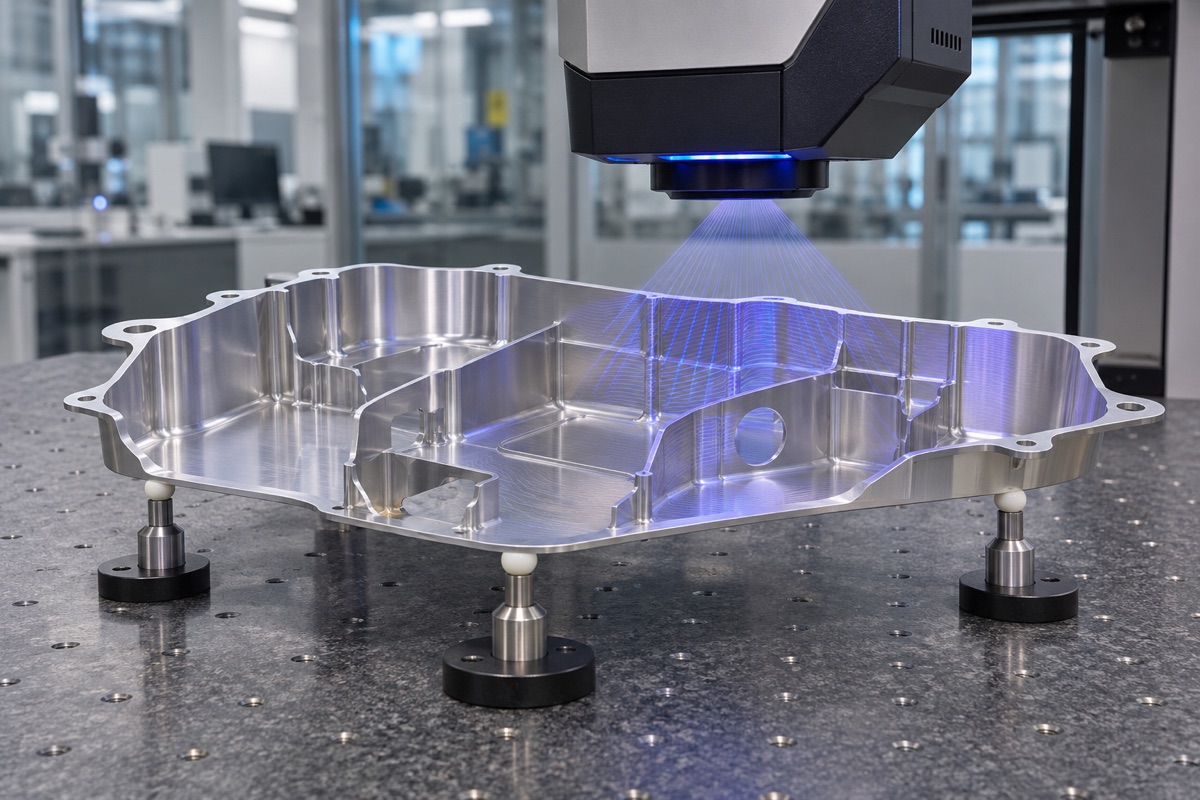
The final results should be re-measured under the agreed state to avoid flattening the parts with the measuring fixture.
Inspection must avoid re-pressing and deforming the parts
Thin wall dimensions may be verified using prescribed supports, low force contact or non-contact methods. The measurement plan should record the support point, direction, temperature, stabilization time and detection force, and compare the clamping state and the loose clamping state. The local wall thickness, overall contour and mounting hole position need to be judged jointly, and one caliper reading cannot be used instead of the free state contour.
Process parameters need to be approved step by step from the first piece
Publicly available information cannot give vacuum values or cutting parameters that apply to all materials, sizes and machine tools. The first part should record vacuum settings, leakage status, tools, loads, outlines at each stage and final dimensions to form an approval window for the current part. When OEMach (OEMach) reviews such projects, it will first check the structure, adsorption area and inspection status before deciding whether to adopt a vacuum solution.
Summary
First define the free state and functional benchmark, and then verify the vacuum plan based on the effective adsorption area; only by adopting low-stress clamping, symmetrical layered removal, coarse and fine separation, and loose clamping and retesting can the results of thin walls less than 1mm be stabilized. The specific process still needs to be confirmed by combining the thin-wall free state, blank residual stress, vacuum effective area, sealing partition, cutting load, rough and fine separation and loose clamp retest.
FAQ
Will the vacuum suction cup deform the thin wall?
It will be possible. If the support surface is uneven, the sealing groove layout is improper, or the pressure difference causes bending of the large-area thin plate, it is necessary to optimize the support and partitions and conduct a free-state retest.
How long does it take to release stress after rough machining?
There is no universal time. It should be determined based on the material state, structure and dimensional trends after rough machining. Recording a stable process is more reliable than applying a fixed number of hours.
Can a certain fixed tolerance be guaranteed if the wall thickness is less than 1mm?
Dimensions, materials, lengths, datums and measurement status commitments cannot be deviated from and must be verified with error budgets and representative first articles.
Ready to get a quote for your CNC machined parts?
Submit your engineering drawings to qiancj@oemach.com. We support prototype sampling and small-batch production with strict tolerance control.