
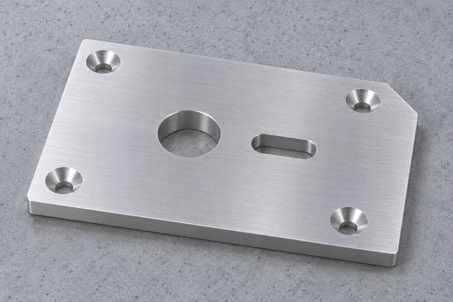
Locate a panel in a bench fixture
A service fixture can support a removable access panel from an anesthesia workstation while a technician checks its fit or verifies that replacement fasteners are accessible. In this example, a 6061 aluminum locator plate mounts to the service fixture, not to the gas path, electronics or working enclosure. The plate has a seating face, a round hole and an oblong slot for two locating pins. Four countersunk mounting holes attach it to the bench fixture. These features serve different functions: attachment is not the same as positioning, and a stable fixture fit is not evidence of machine performance.

Constrain rotation without trapping pin spacing
A round locator sets position in two in-plane directions. A second pin in a slot can constrain rotation while allowing variation along the slot axis. For this arrangement the slot normally lies along the line joining the pin centers. The assembly drawing should show that direction and distinguish slot width from useful length. Compare the allowable pin spacing with the clear travel at both ends. If a slot is rotated away from the intended direction, increasing its length may not prevent binding. A pair of round holes can be suitable in other designs, but the allowed pin spacing must then be controlled accordingly.
Specify which surfaces actually seat
Use the mounting underside as a manufacturing reference when it sets the plate against the fixture. Clarify whether the top face also locates the panel or only provides clearance. If top height matters, define thickness and parallelism where they affect fit. Four countersunk screws can pull a thin plate toward their own centers, so coordinate the screw seating requirement with the location scheme. Overspecifying every hole as a close locator may prevent parts from assembling. Define the orientation corner as an envelope or key only where the mating fixture really uses it. Document the feature priorities in the drawing, not just in CAD.
Rough and finish with distributed support
Start with the specified 6061 stock condition and thickness. Support the blank over a broad area so that the cutter and clamps do not bend it. Check the stock for bow before forcing it against a flat support. Where roughing releases residual stress, consider roughing both faces and checking the released plate before finish passes. Keep clamps clear of the locator path and avoid leaving support marks on the seating face. A plate that measures flat under load can spring back when released. Plan the check in the free state unless the drawing explicitly defines an installed condition.
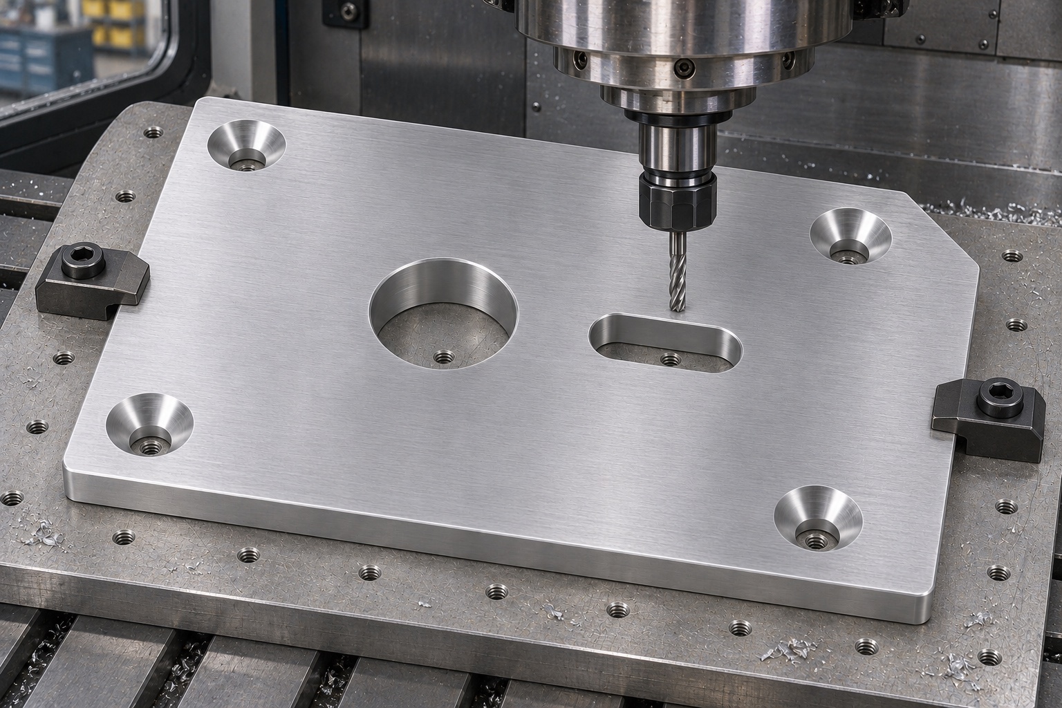
Machine the bore and slot from a common setup
Where access allows, establish both locators while the plate is in one stable setup. This avoids a separate datum transfer between the round bore and the slot. Use a suitable boring, reaming or interpolation method for the bore size and finish; the correct method depends on the released requirements and available tools. Rough the slot and finish its side walls with light, repeatable engagement. Verify actual width and direction, not just cutter center travel. Plan tool reach and chip removal so the bottom edge does not retain a burr. Make the orientation corner from the same outline reference when its location matters.
Control screw-head protrusion
Countersinks should match the specified screw form and leave enough material beneath the head. Check the drawing angle and seating condition rather than assuming all flat heads are identical. A head that appears flush can still contact only at one edge. Use a specified depth or a representative screw to check head position and seating where appropriate. Do not deepen a countersink simply to accommodate a mismatched screw. Examine the underside at the through-hole exit, since a burr there can hold the plate off its fixture. Confirm the complete assembly still locates on the intended pins after screws are seated.
Account for coating where applicable
For custom CNC machining to drawing, ask whether locator surfaces are delivered as machined, masked or measured after coating. A finish can change the effective fit or leave a transition near a seating area. Mark protected surfaces and acceptable contact points on the finish drawing. Avoid guessing an allowance from a generic coating thickness. Deburr before treatment and verify relevant sizes afterward. If the plate is as machined, define the required surface texture and handling protections. The alloy and finish choice do not establish electrical bonding, compatibility with a particular cleaning method or approval for use on a working device.
Measure size, direction and flatness separately
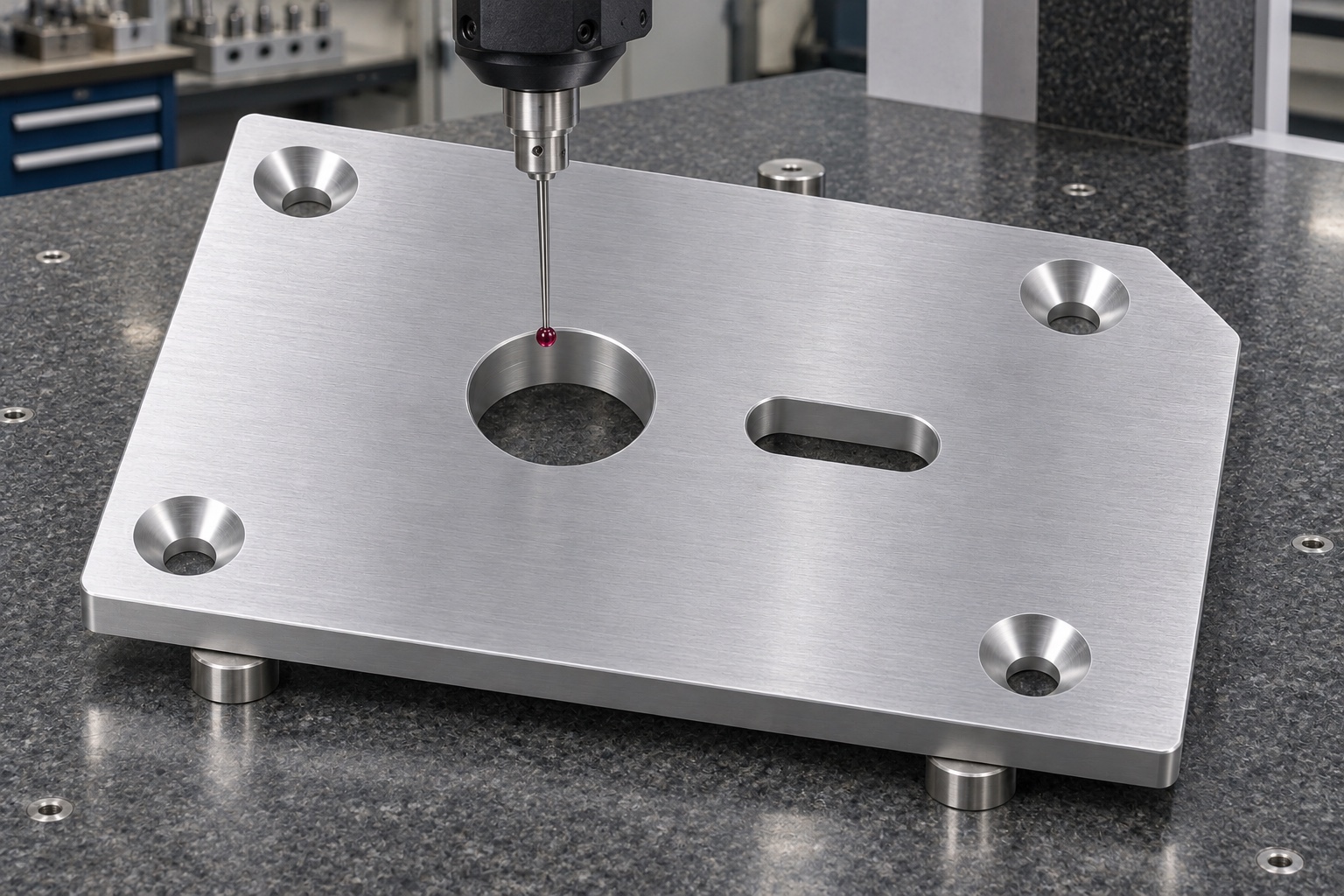
Support the plate as agreed and check the mounting face without bending it flat. On a coordinate measuring machine or a suitable optical system, determine the bore center and sample both straight slot walls. Derive slot direction from the functional wall portions rather than the rounded ends. Check end clearance separately. A pair of gauge pins can supplement the numerical measurements, but passing the pins does not establish flatness or prove that the slot faces the right way across the allowed spacing range. Include the datum setup, measurement condition and finish state in the first-article report.
Run a removable fit check
Place the plate on a representative fixture base and confirm that it seats before tightening. Use the specified pin sizes and check the practical extremes of spacing or document how a gauge represents them. Verify removal as well as insertion, since a plate that can be driven on may not be serviceable. Confirm screw-head clearance against a test panel or envelope. This is a fixture check with non-operational components. It does not evaluate gas flow, equipment safety, electrical grounding or clinical readiness. A service fixture should be used only within its separately defined equipment procedures.
Investigate errors without relaxing the wrong feature
If the round pin enters but the second pin stops, check slot direction, width and position before adding clearance. If both pins pass but the plate rocks, inspect its underside and the fixture seating surface. If the plate seats before fastening and moves during tightening, compare the screw centerlines and seating geometry. Separate part error from fixture error using documented references. A localized witness mark can identify the first contact. Record the confirmed cause before changing program offsets or requesting a drawing revision. On repeat jobs, preserve the correction and inspection setup together.
Make pilot quotations comparable
Include the drawing, stock condition, finish specification, locator pin dimensions and service fixture envelope in the RFQ. Ask for separate pricing for a small pilot, repeat lots and any inspection fixture. Identify whether a first-article report is needed for both faces, the hole and slot, and the countersinks. Specify if a panel surrogate is supplied. A simple geometry may still require careful support and measurement when fit depends on the slot direction. State how the workpiece is to be identified and which surfaces cannot carry marks. Agree on the final acceptance state before pricing a finish.
Preserve the seating faces after inspection
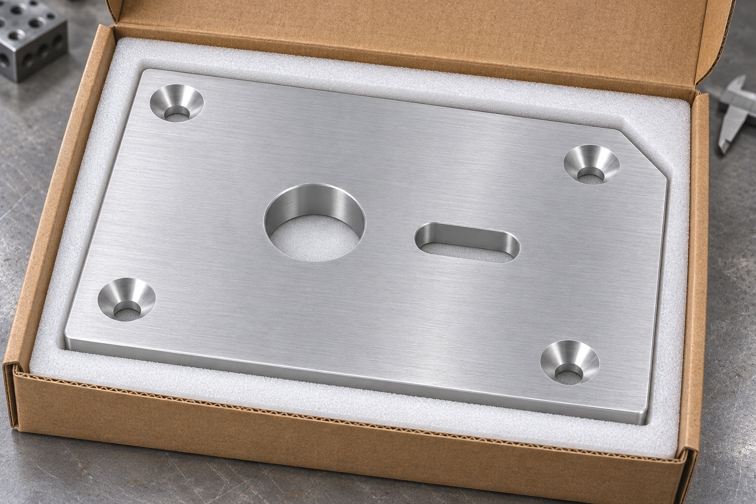
Pack plates flat in separate recesses or with clean non-abrasive separators. Keep loose screws and locator pins out of contact with the bore, slot and seating face. Label the outside of the package with revision and lot identification where specified. Prevent a narrow strap or excessive stacking load from bending the plate. At receiving, check the surfaces for dents and trapped debris before making fit judgments. Repeat the agreed flatness or locator check if the packaging shows impact. The protective package is for ordinary transport and does not claim sterile handling or any device classification.
FAQ
Why use one round hole and one slot?
The round hole locates the plate in two directions. The slot can limit rotation while allowing spacing variation along its length.
Which slot dimension most directly affects rotation?
The width and direction of the functional walls matter. The length mainly provides clearance for pin spacing when the slot is correctly oriented.
Can a screw pattern replace the locators?
Only if the design deliberately defines screw-based location. Ordinary countersunk fasteners should not be assumed to reproduce a dedicated datum pair.
Why check flatness after releasing the clamps?
A clamp can temporarily flatten a bowed blank. The released condition shows the shape the plate brings to the assembly.
Should locators be measured before or after coating?
Use the drawing-defined acceptance state. If coating can affect fit, agree on masking or verify the relevant dimensions after treatment.
Does the fit check qualify a workstation?
No. It checks a removable mechanical service fixture. It does not verify anesthesia workstation operation, patient safety or clinical readiness.

tanghangyun@oemach.com