
Define the stop and release functions
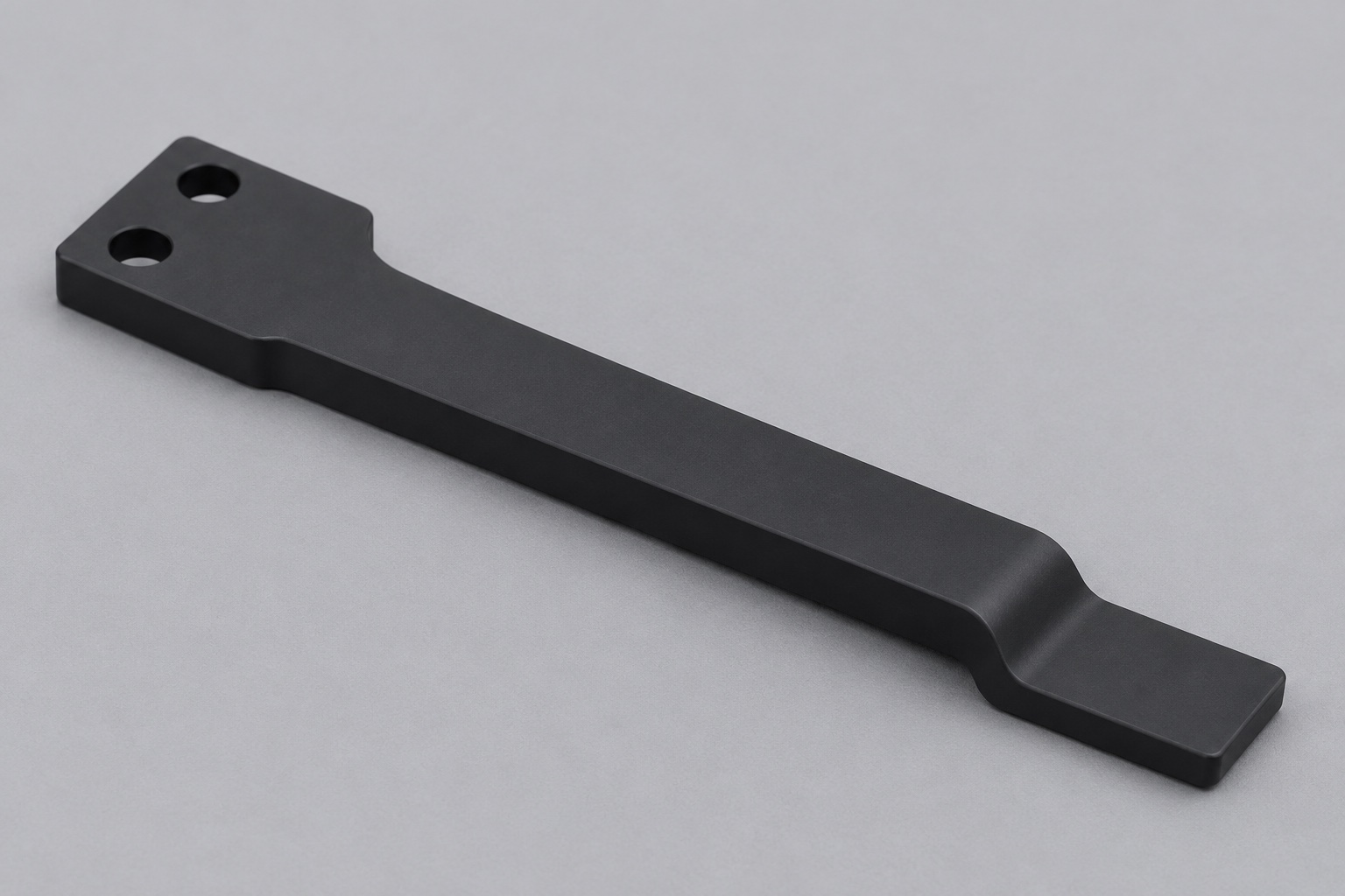
A pathology slide loader can use a slender escapement finger to hold a glass slide at a defined edge until the mechanism releases it. In this example, two holes mount a wider rear pad; a narrow shank reaches forward to a stepped stop nose. The part belongs to the slide handling mechanism, not the optics or the diagnostic workflow. The glass edge is the intended contact location. The coverslip, sample and label zones must stay clear as specified by the equipment design. Precision POM-C CNC milling starts with defining those clearances at the installed positions, not by assigning the same tolerance to every surface of the finger.

Locate the nose from the mounting pad
Use the mounting pad as the primary reference when that is how the actuator supports the finger. Identify whether a guide edge, locating pin or fixture establishes rotation. Two clearance holes are not necessarily locators. Define nose height and lateral offset from the mounting references and include the required contact width. Show the relevant cross section so the specified step is not measured from an unrelated outside surface. If the actuator uses an adjustment, document its available range separately from part tolerances. Making the nose oversized and adjusting each installation by hand can hide a repeatability problem rather than solving it.
Separate part geometry from slide variability
The mechanism may see slides with different edge breaks, thicknesses or attached labels within its specified envelope. Provide the allowed ranges and define which region of the slide may contact the nose. The narrowest contact edge in the envelope can be more revealing than a nominal-width dummy. A nose can appear correctly positioned in a static view while touching a neighboring slide during its return path. Use an assembly model and controlled bench gauges to check the release clearance. Keep the part report independent from claims about jam rate, scan accuracy or other behavior that only the equipment owner can validate.
Support the rear pad and shank during roughing
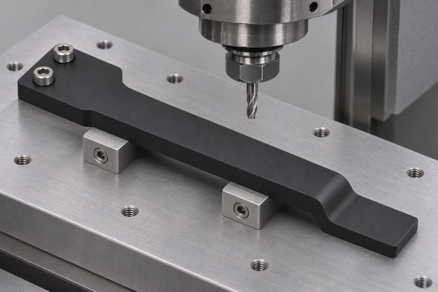
Use the specified grade and stock form of POM-C acetal. On a prototype, machine from flat stock with a stiff sacrificial border or a fixture that supports most of the length. Prepare the two faces without forcing bowed stock flat against a plate. Remove stock in a balanced sequence when trial pieces show movement from one-sided removal. Keep the rough shank wider than its finished profile until the main step and mounting pad have been defined. A sharp tool with good chip clearance helps avoid rubbing and heat buildup. Limit unsupported reach so cutting forces do not simply push the narrow arm away from the cutter.
Finish the nose while its edges are supported
The step forms a broad stop face rather than a sharp point. Choose a finishing sequence that supports the nose until the critical contact profile is cut. Program the transition radius and the final edge break rather than relying on hand sanding to create them. A heavy last cut on a thin unsupported end can produce a tapered or wavy contact band. Plan where the cutter enters and exits so a witness mark is not left across the glass contact face. Preserve the step height when machining the underside. Inspect the profile after removing temporary support, since the nose can move as the remaining stock is released.
Avoid measuring heat and fixture pressure as part geometry
POM-C is a thermoplastic; for close dimensions, let a freshly machined part stabilize at the agreed measurement condition. Record the temperature or conditioning requirement when it is important to acceptance. A fixture that holds the whole shank down may flatten an out-of-plane bow for as long as the clamps are closed. Check free-state profile on repeatable supports under the mounting region and compare it with the required installed condition only when both states are defined. Never force the nose against an inspection plane just to improve repeatability. If readings vary with the support, revise the measurement setup before changing the tool offset.
Inspect burrs without changing the contact height
Look at the stop face, transition and mounting-hole exits under suitable magnification. Loose strings of plastic can remain attached after milling; remove them with an approved tool and avoid trimming a functional edge back by eye. Broad rounding of the nose may reduce the contact band or change the effective stop position. Identify edges that need a deliberate radius separately from those that only need removal of loose material. Keep the part free of grit and mixed chips as it moves to inspection. Where an approved cleaning agent is specified, verify compatibility and follow the equipment owner's component handling requirements.
Use a method that can distinguish edges from shadows
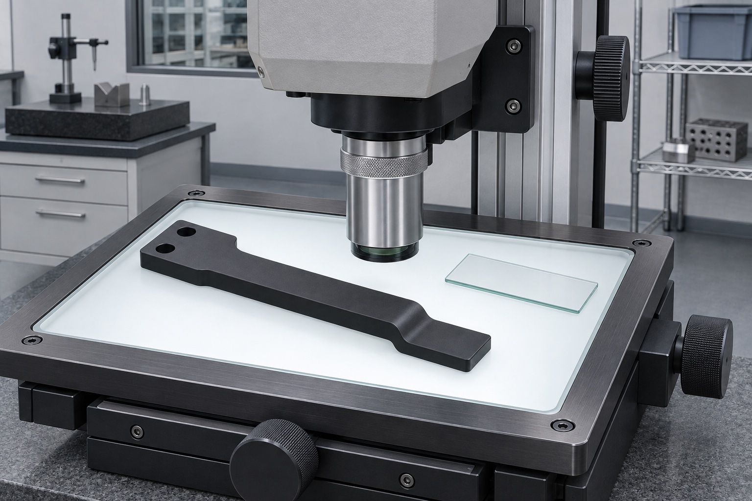
An optical comparator or calibrated vision system can capture the shank profile and nose contour without pushing on a slender part. Validate the lighting and focus on the actual inspection plane, especially with dark material and a stepped shape. Use repeatable supports and verify scale against an appropriate artifact. For step height, use a method that measures height from the mounting pad rather than inferring it from a single top view. If a contact method is required, document the probe load and check that repeated approach does not move the arm. Preserve images or numerical results in the requested first-article record.
Verify travel with clean mechanical surrogates
Use defined dummy slides or dimensional gauges representing the agreed slide envelope. Confirm that the nose stops the intended edge and clears the adjacent slide and neighboring guides throughout the motion. Set the specified mounting torque, support and actuator positions before testing. If it stops correctly in the rest position but catches on release, check the step and motion path before altering the contact width. This is a bench assessment of mechanical clearance, not a device qualification or a study with patient specimens. Set aside any dummy slide with chips or dirt so it cannot change the apparent result.
Diagnose repeated errors by when they appear
A bow that emerges after unclamping suggests a support or stress-release issue. A nose that is correctly profiled but too low only after installation points toward the mating pad or assembly condition. A stop that scratches glass warrants an edge and debris check before increasing clearances. Measure the actual symptom and correlate it with the process step at which it appears. In low-volume custom machining, document stock orientation, roughing order and conditioning interval so the next batch can repeat a proven sequence. Avoid tightening every drawing tolerance as a response to a single unclear failure mode.
Request the evidence needed for a pilot purchase
An RFQ for acetal CNC machining should include the drawing, CAD model, required POM-C grade, slide envelope, intended contact area and measurement conditions. Identify critical dimensions such as pad-to-nose height and the functional profile, and state if an optical image or a tabulated report is required. Supply a mounting coupon or dummy slide when an assembly screen is part of the quote. Keep optional testing separate from the machined part price. Ask how the shop will support the shank and verify the relaxed part. These details are often more useful than requesting the tightest possible dimensional tolerance on every feature.
Pack the finger without bending it
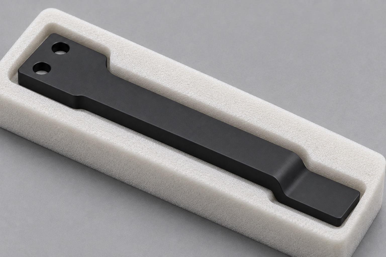
Use a flat tray with a dedicated cavity that supports the pad and shank while leaving the stop face free of pressure. Avoid a narrow tie, loose hardware or a stack that loads the nose. Keep parts separated and identify the revision and material lot on the packaging or traveler. Use only the cleaning and protection requirements agreed for the component, and do not describe this ordinary protective packaging as sterile. At receiving, let parts equilibrate in the measurement area if specified. Inspect the nose for edge damage and repeat the datum-based check if the package shows evidence of a load or impact.
FAQ
Why specify the contact band at the nose?
The nose must meet only the agreed slide edge and clear the rest of the assembly. A vague rounded tip gives no repeatable stop position or contact width.
Why inspect free-state bow separately from installed clearance?
An installed part may be constrained by the actuator and fasteners. A free-state check identifies movement left by machining or handling without confusing it with assembly load.
Is an optical profile enough to verify step height?
Not by itself when the top view only shows the outline. Use a suitable height or depth measurement referenced to the mounting pad.
Can different grades of acetal be substituted?
Only after approval. Confirm the specified grade, stock condition and required behavior rather than assuming all materials sold as acetal are interchangeable.
Does passing a dummy slide check prove scanner performance?
No. It is a limited check of the specified mechanical interfaces. It does not verify image quality, diagnostic performance, long-term wear or complete device reliability.
What should be checked after shipping?
Inspect the stop edge, pad and shank for marks or bow. When packaging was loaded or damaged, repeat the agreed geometry checks before assembly.

tanghangyun@oemach.com