
Identify what actually locates the lever
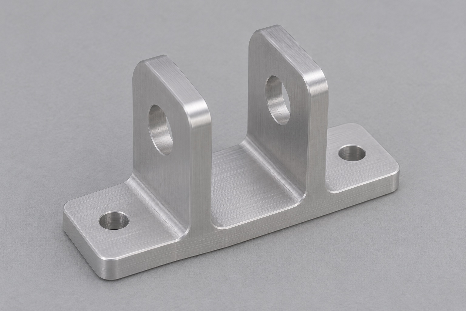
In an illustrative point-of-care analyzer mechanism, a cartridge ejector lever can rotate on a pin supported by two ears of a machined bracket. The base seats on a chassis surface and the gap between the ears accommodates the moving lever. The bracket does not analyze a specimen, seal the cartridge or establish its safe removal. This discussion addresses precision 6061 CNC milling for the mechanical bracket only. Start by identifying what locates the pin, what restrains the lever sideways and where a cartridge surrogate may meet the lever. That separates meaningful manufacturing tolerances from merely convenient dimensions on the outside of the part.

Map the load path to the mounting face
The screw tabs hold the base against a flat mounting surface. Clearance holes usually provide passage rather than exact lateral location; confirm whether a chassis shoulder, separate dowels or an assembly tool positions the bracket. A screw pattern that fits can still allow the pivot to shift if the locator is missing. Put the primary datum on the seating face and select secondary and tertiary references from the features that actually locate the bracket. Locate the pivot axis to that datum system. Consider loads applied at the lever and at its travel stops separately so that a clearance feature is not inadvertently asked to react an operating load.
Separate bore size, axis alignment and ear gap
Two bores may have acceptable diameters while their axes are offset. The pin can then bind even though each hole passes a size gauge. Control the paired pivot bores with requirements that define their relationship to the base and to one another. Set the gap between the inner ear faces independently. Its tolerance should account for the width of the lever and any intended washers or spacers. Also specify pin engagement, the direction of insertion and the retention method. If one hole is intended to retain the pin and the other is a clearance bore, do not assign both the same fit simply to simplify tooling.
Support a one-piece blank during pocketing
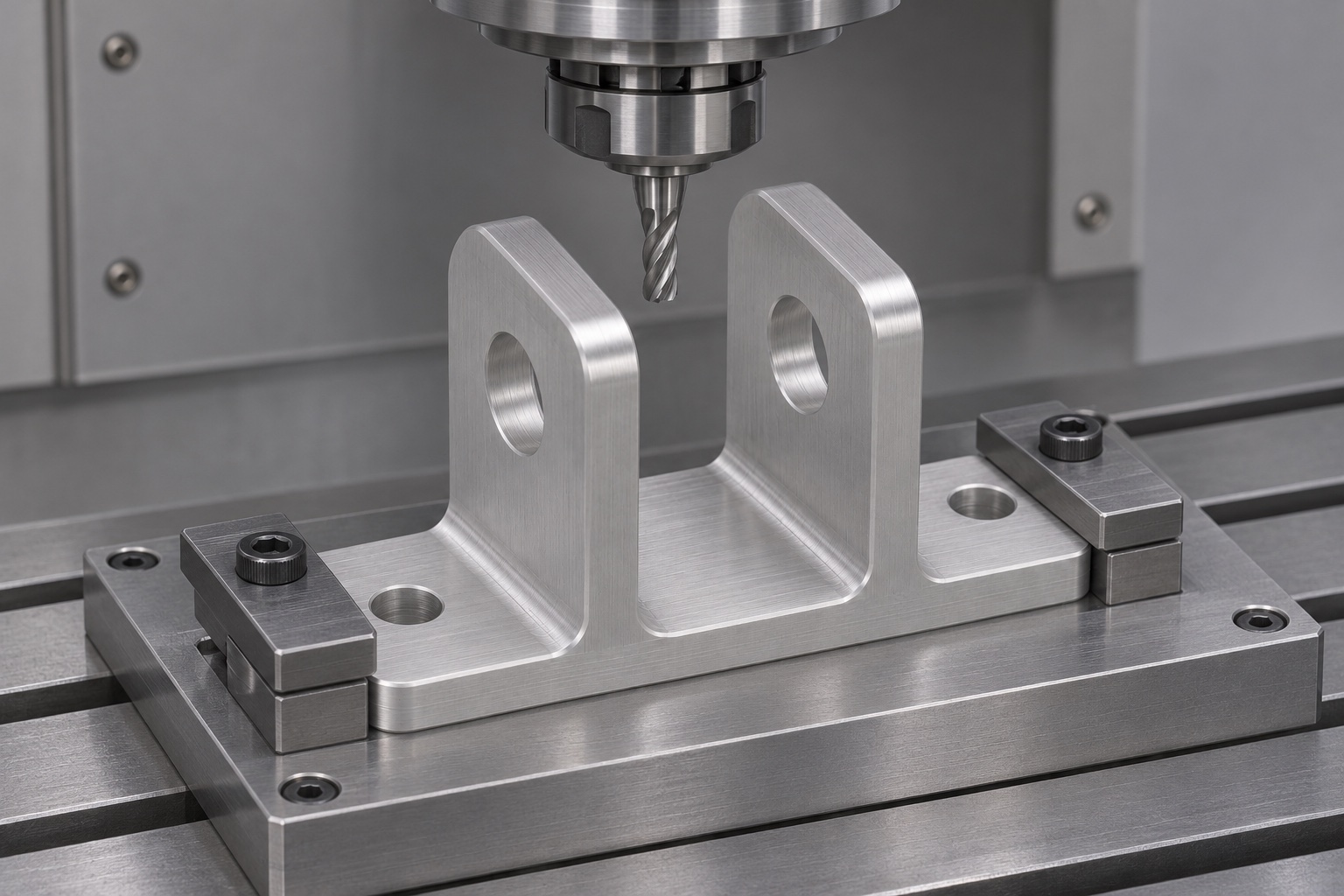
One approach uses a billet and leaves the mounting tabs integral with the base. Establish a reliable bottom datum, then grip or fasten the stock where the future base is strong. Rough the central channel before thinning the ears to their final thickness. Remove material in a sequence that keeps support reasonably balanced on both sides. A deep cut against a nearly finished unsupported ear can move the wall away from the cutter and produce taper. Use a cutter sized for the channel and specified root radius. Check reach against both ears and allow chips to leave the pocket instead of being recut near the final faces.
Plan side access to finish the pivot bores
For a CNC machined U bracket, a qualified right-angle setup or a rotated fixture can establish the bore direction. In suitable geometry, one aligned tool path through both ears avoids an extra datum transfer. It still requires checking tool reach, evacuation and deflection in the second ear. A drill entering the second wall across an open gap may wander; use an appropriate preparation and finishing sequence rather than assuming a through pass guarantees alignment. If opposite-side operations are unavoidable, establish a common datum and verify it after rotation. Record the setup and measurement strategy before requesting a tight axis relationship that may be expensive to produce.
Check finishes where clearance is smallest
Deburr both entries and exits of each bore, including the faces inside the channel. A burr on the inner wall can scratch a lever or imitate inadequate gap. A large hand-applied chamfer can shorten the effective bearing length. Specify the allowed edge break and choose tools that can reach the two inner edges without touching the opposite ear. If anodizing is required, state which surfaces are treated or masked and whether tolerances apply after treatment. A coating plan for the base is not necessarily suitable for a close pin bore. Measure the actual finish condition required for assembly.
Decide how the lever can be serviced
An open channel does not guarantee assembly access. Verify that the pin can travel along its insertion axis with a tool or removal feature in place. Check the space around the retaining element and ensure the ears leave room for the lever to swing. Check both the installed condition and the service condition with neighboring panels removed as permitted by the design. An exterior mounting tab that meets its envelope can still obstruct a hand tool. Capture these restrictions on the assembly model and share the relevant envelopes with the machine shop. Do not use unnecessary tight tolerances as a substitute for a missing access requirement.
Measure the axis from the working references
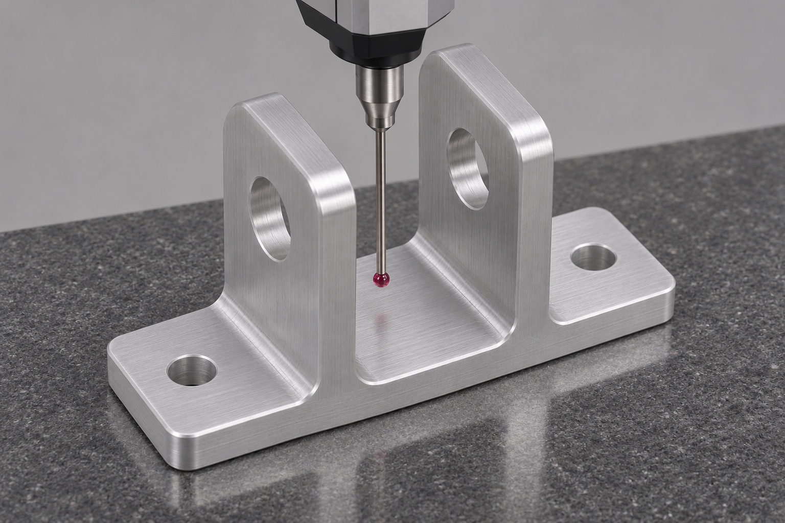
Set the bracket on its mounting face with stable, non-distorting restraint. On a coordinate measuring machine, probe each bore with a suitable stylus and sample enough of its cylindrical surface to estimate an axis; avoid the chamfers. Confirm that the chosen probing paths fit between the ears and that stylus length and uncertainty suit the requirement. Include actual ear gap and axis height in the report. A straight master pin across the pair is a useful functional supplement when its diameter and force condition are specified. It cannot on its own locate the bore pair relative to the mounting face or distinguish errors in the two bores.
Test fit with a cartridge surrogate
Use a defined pin and a dummy lever, or an approved build fixture, for mechanical fit. Confirm the pin can be inserted without forcing the ears together and that the lever clears both walls through its expected travel. Check an agreed empty cartridge surrogate where the lever approaches or releases it. Document the pin, lever and surrogate revisions. If movement is tight only when the base is bolted down, check chassis contact and seating before modifying the bores. This operation can help find interference. It is separate from verifying sample containment, assay accuracy, ejection life or medical device performance.
Resolve deviations by feature, not by feel
If each bore passes but the pin stops at the far wall, compare the measured axes before reaming larger. If the lever moves freely off the bracket but scrapes in assembly, inspect the inner faces, spacer stack and pin retention. If the bracket rocks on the chassis, measure the underside for burrs or bow and check the mounting surface itself. These defects have different causes and corrections. Rework should not be used to widen a tolerance without authorization. Capture the observed symptom and the confirmed source so tooling corrections do not mask an error in the fixture or another component.
Order pilot parts with a specific report
An RFQ for custom CNC machined medical equipment parts should include the drawing, CAD revision, required 6061 stock condition, finish, mating pin details and mounting interface. Ask for a first-article report that gives values for both bores, their relationship, the channel width and the seat. Specify if function should be checked before or after any coating. Compare a quote with a dedicated side-bore fixture against one with a carefully measured reorientation. Low-volume machining may favor a setup that is easy to validate rather than one optimized for cycle time. Retain the pilot route and the acceptance records for follow-on lots.
Protect the ears and seating surface in shipment
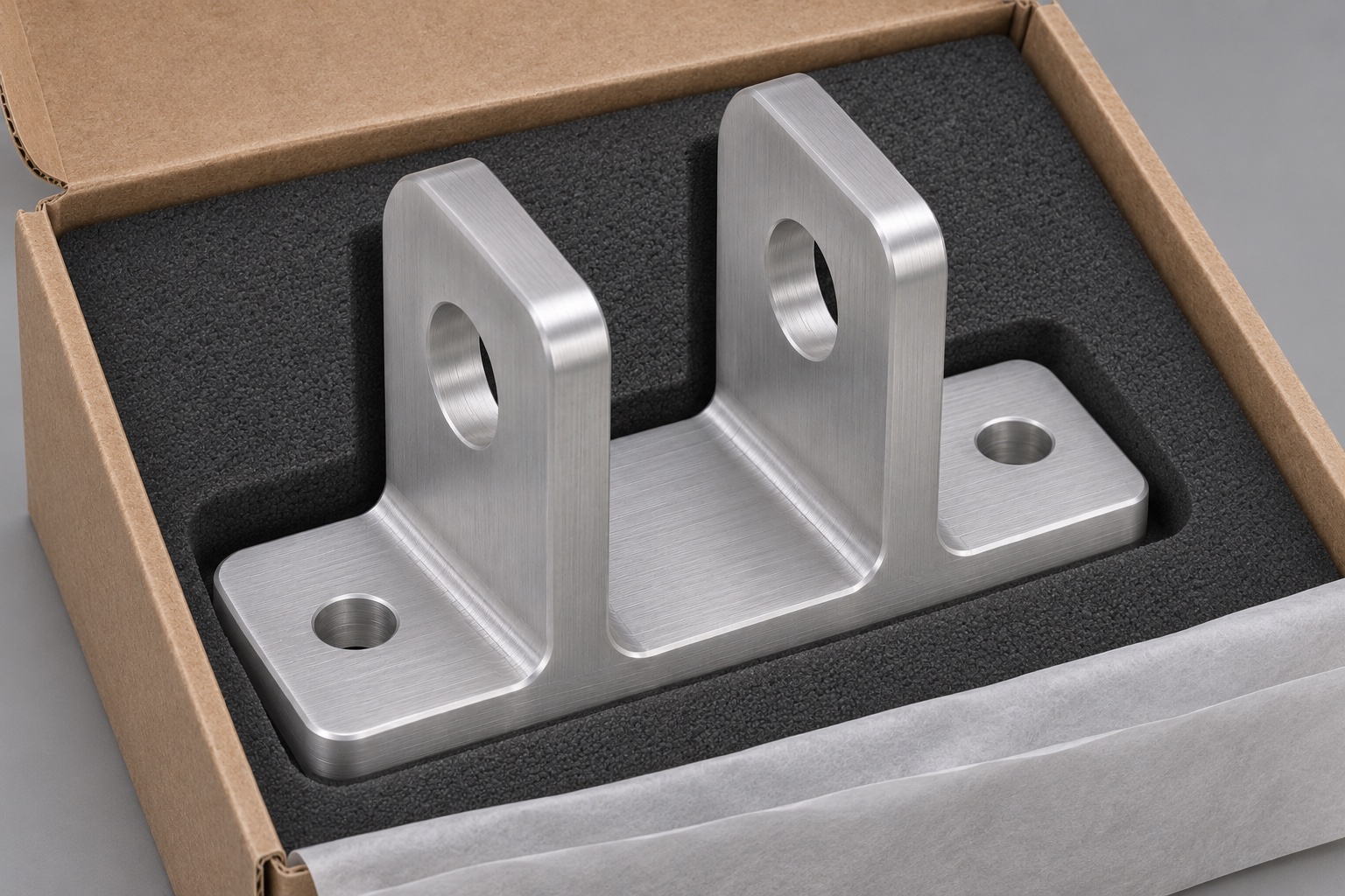
Use a tray or soft separators that restrain the base and do not press against the tops of the ears. Keep threaded fasteners and pins in separate pockets unless a retained subassembly is specifically requested. Avoid stacking brackets on their seating faces, since a dent or trapped chip there can change installed axis height. Keep the final finish and lot information with the shipping record. This packaging protects a mechanical component from handling damage; it is not evidence of sterile processing. At receiving, inspect the bore entrances, seat and ears before seating the part on a master and repeating the agreed fit check.
FAQ
Why can two acceptable pivot bores still bind?
Size inspection alone does not establish the relative axes. A pin must cross both bores and can be blocked by offset, angular error or an inner burr.
Should both bores be finished in one pass?
It can reduce reorientation error if access and stiffness are adequate. A process trial should verify the second bore rather than assuming the long tool stays on axis.
Can mounting screws locate the bracket accurately?
Only if the design defines a locating feature and its fit. Standard clearance holes allow movement and should not be assumed to provide repeatable lateral location.
What should be measured after anodizing?
Measure the drawing features affected by finish, especially pin fits and relevant seating surfaces. Follow the specified masking and final acceptance requirements.
Does a master pin verify the pivot height?
No. It may confirm passage under a stated fit condition. Relate the bore axes to the mounting datum with a suitable measurement method to verify height.
Is a cartridge fit check a diagnostic performance test?
No. It detects mechanical interference under the defined fixture conditions. It does not establish assay performance, containment or field reliability.

tanghangyun@oemach.com