
Start with the barrel and its support
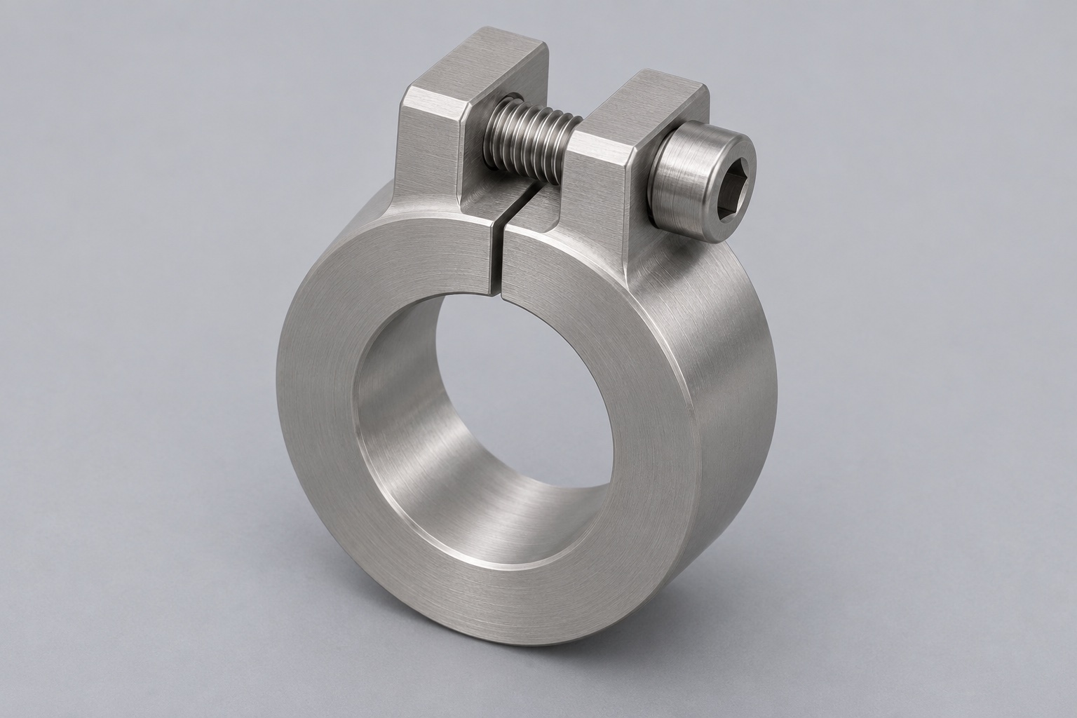
A dental handpiece service bench can use a split collar to support a round dummy barrel while a technician evaluates fixture fit or access. The bore provides radial location; a screw across a radial slit closes the two ears. The bench structure should carry reactions that the collar is not meant to resist. For precision CNC machining, define which barrel zone may touch the collar and which ports, flats or fragile surfaces must remain clear. The finished collar is a bench fixture component, not a rotating handpiece part or a patient-contact component. No clinical or device performance follows from a good fit on a dummy barrel.

Specify both bore states
A free-state diameter is useful only if the drawing defines the screw condition and leaves the slit free to move. A clamped-state dimension depends on the master diameter, screw, lubrication and closing procedure. Ask which state each dimension describes. A ring that accepts the nominal barrel with the screw removed can still have insufficient remaining slit travel at the upper or lower end of the diameter range. Conversely, passing a pin through a squeezed collar says little about insertion without force. Treat entry clearance, axial seating and closing travel as separate checks instead of expecting a single tight diameter to settle all three.
Choose datum surfaces that survive the slit
The axial face can serve as a stable seating reference if the collar bottoms on a bench shoulder. A bore axis derived from the intact part of the cylindrical surface may be useful for orientation and runout checks. Define the sampling exclusions around the split and chamfer. If the collar has to be clocked, use a specified ear face or separate fixture key rather than guessing from an irregular saw edge. Establish these references in the drawing and reproduce them in the machine and at inspection. Selecting a visually convenient outside diameter that does not locate anything in the fixture can hide the actual error.
Turn the bore while the blank is stiff
For 316L stainless steel CNC turning, begin with enough stock for the integral pinch ears and hold the blank on a rigid land. Rough the bore, face the seating surface and leave finish allowance where the process trial shows movement. Where the tool and blank permit, finish the bore and axial reference face from the same spindle setup. Program a real cutting engagement; a tool that rubs a work-hardened surface can give an inconsistent finish. Keep chip evacuation clear of the bore entry. A boring bar that fits with useful stiffness is preferable to an unnecessarily long reach simply because it fits the machine.
Mill ears before opening the collar
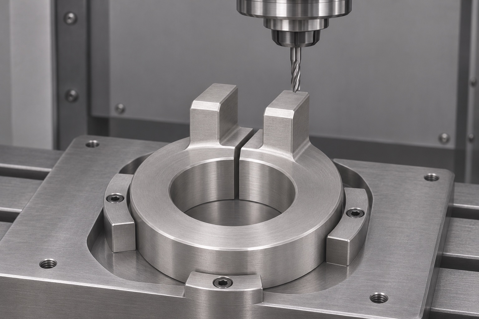
Move the blank to a supported nest that references the face and bore or a verified transfer diameter. Mill away the excess outside material to expose two integral ears. With the collar still closed, make the transverse clearance hole and the matching threaded hole using the agreed thread preparation. Account for the head seat and tool exit path as well as the nominal screw axis. A threading process that leaves loose fragments beside the future split creates avoidable cleanup. Preserve enough material at the roots of both ears, and do not use the ear tips as the sole support when machining their sides.
Treat the final slit as a release operation
Cutting through the wall releases the blank's closed hoop. Slit width and the resulting free-state bore may change after the cut and after unclamping. On prototypes, record diameters and slit width before and after the release, then compare the trend across more than one piece before assigning compensation. A slit cut with excessive side load can also deflect the tool and leave different widths at entry and exit. Support the collar body without preloading the ears. Do not close the slit against a spacer simply to make the part measure well; doing so can conceal the very movement the check is meant to catch.
Break only the edges that need it
Specify separate edge treatment for the bore mouth, the two interior slit intersections, screw entry and outside handling edges. A burr inside the bore can score a dummy barrel even when the rest of the cylinder meets size. Abrasive polishing by feel can alter contact length or round a seating face. Choose a deburring method with direct access to the intersection and inspect under angled light after cleaning. Keep ferrous contamination away from stainless steel finishing operations. If the drawing calls for a surface treatment, define the applicable procedure and confirm that final dimensional acceptance takes place after it, not just before.
Inspect without squeezing the ring
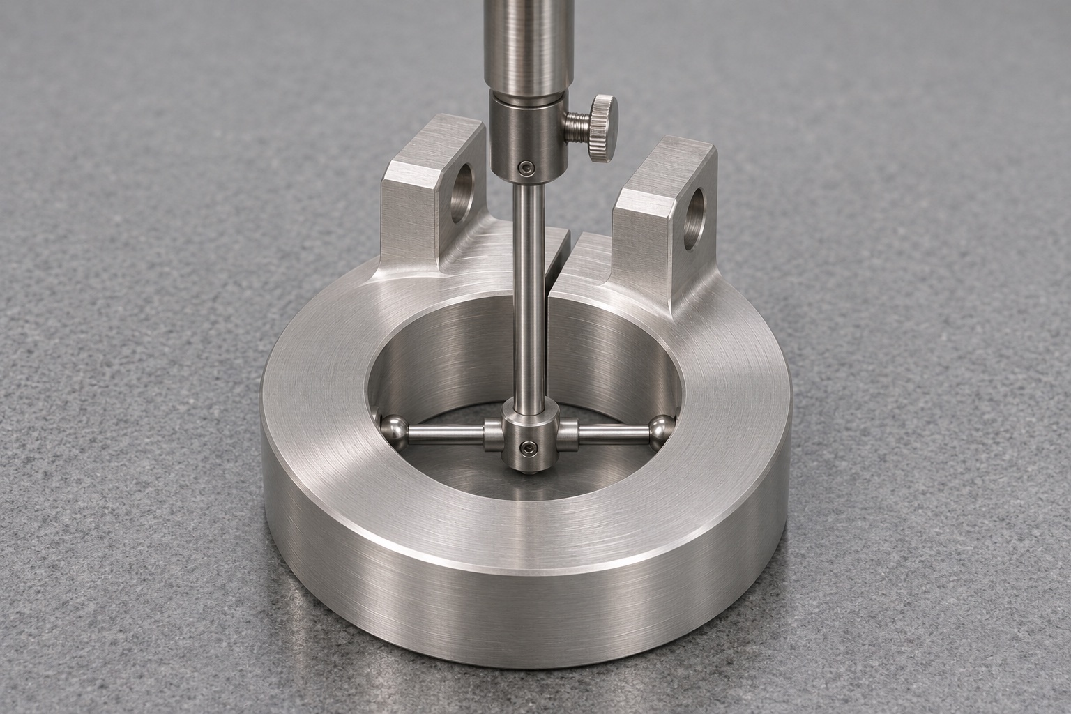
Locate the collar on its seating face with no screw load. A bore gauge can report diameters away from the slit; use several directions and depths instead of trusting one value. For tighter form requirements, agree on a suitable scanning method, the treatment of points near discontinuities and the permitted probe load. A heavily spring-loaded gauge can itself move a thin collar. Record the slit width at the specified locations and note which results come from the free state. Repeat the seating on a second check to distinguish fixture bias from a stable part feature. Keep a measuring mandrel separate from shop handling tools.
Check the assembly without inferring device performance
A controlled fixture trial can use a master cylinder or a protected dummy barrel with the right diameter and shoulder shape. Confirm straight insertion, shoulder seating, access to the screw and the remaining slit gap after closure. If the collar is used with a liner, use the correct liner revision and inspect whether the liner bridges the slit. The fit test should state the assembly sequence, screw condition and any approved limit on tightening. Stop if the screw bottoms out or the ear faces touch before support is established. A bench fit result is not evidence of vibration endurance, fluid sealing or safe use on a clinical device.
Use pilot data to choose the final sequence
Custom machining to drawing benefits from recording variation by operation. Compare the turn-only bore, the bore after ear milling and the final free-state bore. A trend that appears only after slitting points to material release or setup load; a trend already present after turning points elsewhere. If the bore needs a final correction after the split, qualify a repeatable support condition and demonstrate that the result remains acceptable once released. Keep the same stock condition and orientation for the pilot, and document both. Avoid tuning an offset against one anomalous part and then carrying that offset into a new lot without review.
Quote features and evidence separately
An RFQ for low-volume CNC split collars should include the drawing, mating barrel envelope, allowed contact band, screw specification, required closing condition and inspection deliverables. Indicate which surfaces remain as machined and which require a particular roughness. A request for a complete first-article report has different setup implications from a request for a bore check and visual edge review. Ask separately for an assembly fixture check if a master is available. Quote optional alternate sequences, such as a post-slit finish operation, only where the required evidence justifies them. Specify whether the screw is supplied fitted, loose or omitted.
Preserve the bore and ears in transit
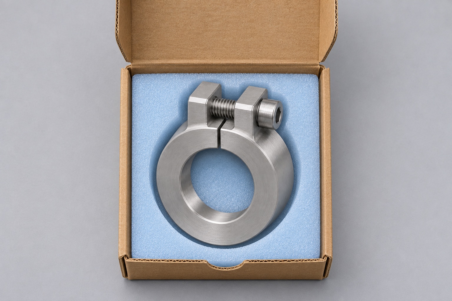
After final cleaning and inspection, use separate pockets that support the collar body rather than levering on the pinch ears. Keep the bore mouth away from hard fixtures, and isolate any loose fastener so it cannot strike the contact surface. Avoid packing with a screw tightened against an empty bore unless the assembly specification calls for that condition. Match outer labels to the part revision and material lot; place inspection documents where they cannot rub the machined part. This is handling protection for a fixture component, not sterile packaging. Inspect the slit and reference face again after unpacking if they are essential to the next assembly step.
FAQ
Why measure the collar with the screw removed?
It separates machining and release effects from assembly preload. If the drawing calls for a different free-state screw position, record that exact position instead.
Can a plug gauge establish roundness at the split?
No. It checks a fit condition under its own contact geometry. Use a form measurement method with agreed sampling and exclusions when roundness is a requirement.
Should the slit be machined before boring?
Often the blank is easier to bore while closed. The choice depends on release behavior, the specified bore state and whether post-slit finishing can be controlled.
What should a dummy barrel reproduce?
Include the working diameter range, axial shoulder and any relief or contact boundaries relevant to the fixture. A smooth cylinder alone cannot check every assembly interface.
Does 316L alone define the finish?
No. The drawing should specify surface condition, relevant roughness and any post-machining treatment. The material designation by itself does not describe cleanliness or acceptance.
How can transit damage be detected?
Look for shifted slit width, impact marks at the ears and scratches on the bore mouth or datum face. Remeasure a critical interface if any evidence of impact is found.

tanghangyun@oemach.com