
±0.01 mm is a total tolerance bandwidth of 0.02 mm for bilateral dimensions, but the same number is used for shaft diameters, deep holes, thin-walled grooves or large-span locations, and the manufacturing and measurement difficulties are not the same.
There is no "±0.01 mm manufacturer list" that is independent of material, size, structure and batch size; supplier capabilities must be defined by specific characteristics and proven with reliable measurements and process data across time. The specific process still needs to be combined with the applicable characteristics of ±0.01 mm, datum and size definition, material and structure, machine tool thermal state, tool wear, clamping repeatability, measurement uncertainty and process distribution confirmation.
Typical problems, causes, controls and evidence
| Problem | Likely cause | Control action | Acceptance evidence |
|---|---|---|---|
| The first article reaches ±0.01 mm but the batch drifts | Thermal conditions, tool wear or compensation means are close to specification boundaries | Warm up and establish trend control, set guard bands and tool change rules | Time series size, temperature, compensation and tool change recording |
| Equipment accuracy is very good but parts are still out of tolerance | Clamping, structural stiffness, material stresses and datum transformations over equipment effects | Make error budgets based on specific characteristics and optimize supports, processes and benchmarks | Machine tool status, fixture repeatability, unclamp retest and characterization data |
| Measurement results change repeatedly | Insufficient gage capability, temperature, support, or measurement definition | Select gage with matching characteristics and verify repeatability and uncertainty | Calibration, environmental, measurement system analysis and review reports |
First define the 10 micron tolerance completely
When ±0.01 mm is used for linear dimensions, it usually means that 0.01 mm is allowed above and below the nominal value, and the total bandwidth is 0.02 mm. Drawings should also clearly define dimension definitions, datums, inclusion relationships and measurement status. ISO 286-1 gives the linear dimensional tolerance and fit system, and ISO 14405-1:2025 specifies the GPS expression of linear dimensions. Acceptable dimensions do not automatically prove acceptable roundness, position, or orientation.
Feature type determines process difficulty
Short shaft outer diameters, through holes, deep blind holes, thin-walled grooves and large-span holes have different requirements for tools, support and measurement. The same ±0.01 mm may be easier to control when used on a 10 mm rigid shaft, but the risk is higher when used on an open thin-walled housing or a post-processed fit. Inquiries must also provide feature dimensions, materials, heat treatment, surface treatment and quantity.
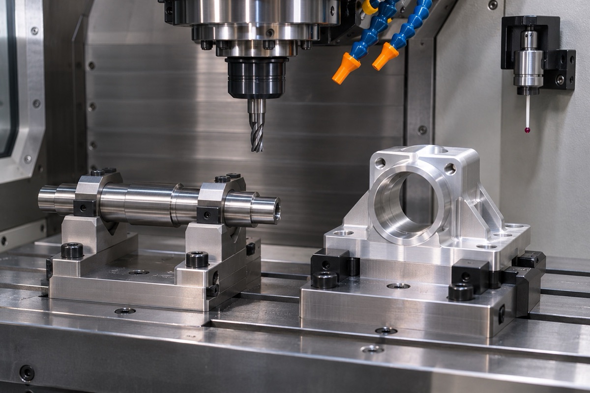
The 10 micron level results come from the joint control of equipment, tooling, tools and thermal conditions.
Equipment accuracy is only part of the error budget
Machine tool geometry and repeatable positioning influence the results, as do setup repeatability, tool runout, cutting forces, material stresses and datum conversions. The supplier should explain in which process the critical dimensions are completed, whether they are processed with clamping, and whether the workpiece is retested after it is unclamped. Equipment nameplate or control system resolution cannot directly equate to part tolerance capabilities.
Thermal conditions and tool life determine batch drift
Changes in temperature of machine tools, parts, fixtures and gages can cause dimensional deviations. The thermal state needs to be stabilized before processing, and critical dimensions should be avoided during the violent heating stage. Tool wear causes the mean to gradually shift, and compensation can only handle predictable trends. Trial production should cover sufficient time and tool life, and keep the average value within the inner guard band of specifications.
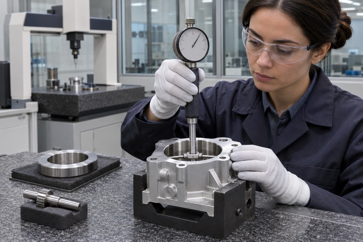
Gage capabilities and measurement methods must match the specific characteristics.
Measurement systems must match characteristics and tolerances
High measuring tool resolution does not mean low measurement uncertainty. Calibration, repeatability, operator, support, temperature, measuring force and method should be considered. ISO 14253-1 specifies conformity decision rules that take into account measurement uncertainty. When it is close to the specification boundary, it should be handled according to the agreed guard band or retest process, and you should not just look at the last digit on the screen.
When evaluating manufacturers, ask for evidence rather than slogans
Allow the supplier to select a similar characteristic describing materials, equipment, tooling, tooling, measurements and continuous data. Looking at first-piece and follow-up trends, measuring tool capabilities, exceptions, and tool change records is more effective than asking "Can it be ±0.01?" The OEMach's capability commitment should also define characteristics, size ranges, lot sizes, and inspection methods.
Summary
There is no "±0.01 mm manufacturer list" that is independent of material, size, structure and batch size; supplier capabilities must be defined by specific characteristics and proven with reliable measurements and process data across time. The specific process still needs to be combined with the applicable characteristics of ±0.01 mm, datum and size definition, material and structure, machine tool thermal state, tool wear, clamping repeatability, measurement uncertainty and process distribution confirmation.
FAQ
Is ±0.01 mm equal to the total tolerance of 0.01 mm?
No. Symmetrical ±0.01 mm bilaterally typically corresponds to a total tolerance bandwidth of 0.02 mm.
If the three-dimensional coordinates can display microns, does it mean it will be accepted?
Not necessarily. Also look at the mission measurement uncertainty, probe, support, temperature and feature definition.
Can a first piece pass prove stable capability?
No. Data across time, tool life, setup and batch are needed to prove that the process is in control.
Ready to get a quote for your CNC machined parts?
Submit your engineering drawings to qiancj@oemach.com. We support prototype sampling and small-batch production with strict tolerance control.