
DFM does not change complex designs into simple designs, but exposes manufacturing and testing risks in advance while maintaining the same functions, and transforms requirements that cannot be modified into clear process plans.
Effective DFM must give reasons, effects and alternatives, which are jointly confirmed by design, manufacturing and quality; any tolerances or structural modifications should go back to the functional and assembly requirements and not be determined by the processing party alone. The specific process still needs to be confirmed by combining functional benchmarks, tolerance necessity, tool accessibility, deep cavities and thin walls, internal fillets, clamping space, inspection accessibility, material status and surface treatment dimensional chain.
Typical problems, causes, controls and evidence
| Problem | Likely cause | Control action | Acceptance evidence |
|---|---|---|---|
| High price and long delivery time | Deep cavities, long knives, thin walls and tight tolerances require special tooling and inefficient processes | A feature-by-feature review of aspect ratios, fillets, wall thicknesses, and tolerances to provide manufacturable alternatives | DFM Issue List, Cost Implications, Approval Conclusions and Design Versions |
| Parts can be machined but cannot be reliably inspected | The datum is too small, the probe is not reachable, or the feature is incompletely defined | Plan the fixture and measurement datum at the same time during the design stage to confirm the accessibility of measuring tools. | Measurement protocols, probe simulations, benchmark repeatability and acceptance methods |
| Poor fit after surface treatment | Coating, masking or heat treatment distortion does not enter the dimensional chain | Write the post-processing type and allowance into the drawings and processes, and re-inspect the key dimensions after processing | Processing specifications, masking diagrams, front and rear dimensions and batch certification |
DFM first confirms that the function cannot be lost
The review should begin by marking out the force transmission paths, bearing and reducer interfaces, seals, sensor mounting, cable space and maintenance requirements. Manufacturing recommendations must describe the impact on these functions. If a thin-walled or deep cavity serves a necessary function, a dedicated process should be retained and designed, rather than deleted directly for the sake of better processing.
Tolerances should be bound to assembly and measurement definitions
Each tight tolerance should answer what failure mode is controlled, which datum is referenced, and in what state it is measured. Dimensional tolerances, geometric tolerances and surface roughness are not substitutes for each other. Simply writing uniform tight tolerances in the title block increases machining and inspection costs, and may also allow non-functional features to take up process capacity. ISO GPS rules can be used to unify drawing representation.
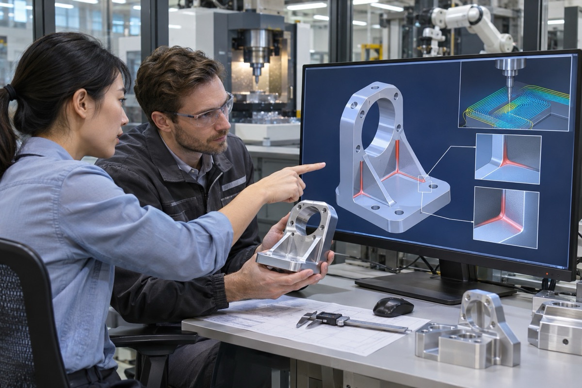
DFM should discuss function, processing and inspection in the same model.
Tool accessibility determines deep cavity and fillet costs
Deep, narrow cavities require long tools, which reduce stiffness and increase vibration; sharp internal corners require extremely small tools or alternative processes such as discharge in milling. DFM can increase the impact of rounded corners, open tool paths, split assembly or retain special processes. Vendor guides such as Protolabs can be used to understand general design constraints, but their dimensional boundaries only represent specific service capabilities.
Clamping and measurement space must be retained in the model
Parts require stable positioning surfaces, clamping areas and tool setbacks, and inspection also requires probes or measuring tools to be accessible. If all surfaces are defined as functional surfaces on the design side, but there is no area that allows for clamping and datum establishment, manufacturing will rely on temporary pressure plates and multiple alignments. Fixture, tool and probe paths can be simulated simultaneously during model review.
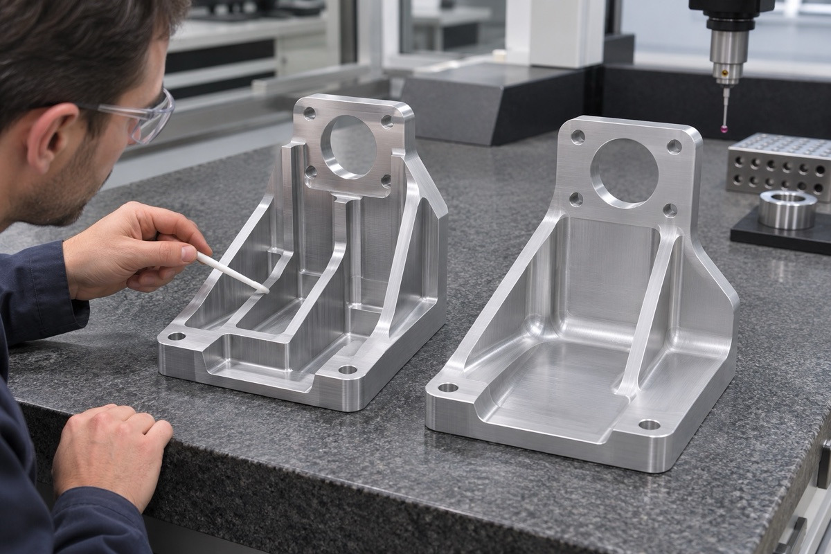
Optimization solutions should account for manufacturing gains while maintaining functionality.
Material and post-processing enter the same size chain
Material condition affects residual stresses and tool selection, and heat treatment, anodizing, plating or passivation can change dimensions and surface. DFM should clarify the status, masking, margin and post-processing re-inspection before and after processing, rather than leaving post-processing to purchasing notes. Different batches may also require different blanks and tooling solutions.
Review output should be able to close the issue
Each issue should record the original design, risks, proposed solutions, cost or cycle impact, responsible persons and approved conclusions. OEMach's process suggestions should be divided into three categories: those that must be modified, those that are recommended to be optimized, and those that can be processed according to the original drawings, and provide the basis for special tooling, cutting tools, and inspection requirements that are executed according to the original drawings. The final version needs to be reconfirmed to prevent old suggestions from continuing to flow into production.
Summary
Effective DFM must give reasons, effects and alternatives, which are jointly confirmed by design, manufacturing and quality; any tolerances or structural modifications should go back to the functional and assembly requirements and not be determined by the processing party alone. The specific process still needs to be confirmed by combining functional benchmarks, tolerance necessity, tool accessibility, deep cavities and thin walls, internal fillets, clamping space, inspection accessibility, material status and surface treatment dimensional chain.
FAQ
Does DFM mean that tolerances must be relaxed?
No. The tolerances required by the function should be retained, and DFM helps confirm whether their definition, process and testing are reasonable.
Can the minimum wall thickness given by the supplier be universal?
No. It relates to materials, dimensions, construction, setup, tooling and equipment and should be verified for specific parts.
Is it too late to do DFM after the model is completed?
It can be done, but the benefits will be greater before the design is frozen; the later it is modified, the higher the cost of version, trial production and certification will be.
Ready to get a quote for your CNC machined parts?
Submit your engineering drawings to qiancj@oemach.com. We support prototype sampling and small-batch production with strict tolerance control.