
The main risk with long structural parts comes from the dynamic system formed by the workpiece, tool and fixture. Simply reducing the feed may temporarily reduce vibration, but it cannot solve the support, modal and free-state deformations.
Geometric accuracy requires machining around a functional datum under controlled support and temperature, and acceptance using a measuring system suitable for the size range in the free state or specified assembly state. The specific process still needs to be combined with the dynamic stiffness of the long cantilever structure, support points, clamping pre-deformation, tool extension, cutting excitation, residual stress, reference system and large-scale inspection and confirmation.
Typical problems, causes, controls and evidence
| Problem | Likely cause | Control action | Acceptance evidence |
|---|---|---|---|
| Periodic vibration patterns appear during long arm machining | The structure or tool mode is close to the tooth passing frequency, and the protrusion and support stiffness are insufficient. | Shorten the tool, optimize the support and tool path, and identify the stable speed zone through trial cutting | Vibration signals, parameter versions, surface and tool wear records |
| When clamped, it bends after being loosened. | The tooling is forced to flatten the blank or remove the material to release residual stress. | Define the free state, use repeatable low-stress supports, separate rough and fine parts and release the clamp for retesting | Support position, clamping sequence, pre- and post-clamping contours and stabilization time |
| The positional relationship between the interfaces at both ends is out of tolerance. | Reference conversion, long-distance measurements and temperature gradient overlay | Process around functional benchmarks, unify support and temperature, and adopt measurement solutions suitable for the size range | Baseline establishment, ambient temperature, CMM or laser measurement and review data |
The long cantilever structure first defines the measurement state
Long arm parts can undergo visible deformation due to weight, support and temperature. Drawings and inspection protocols should illustrate the free state, specified supports or assembled states, and define primary datums, auxiliary datums, and critical joint interfaces. ISO 5459:2024 specifies the expression logic for datums and datum systems, and ISO 1101:2017 provides a language for shape, orientation and position tolerances.
The workpiece and the tool together form a vibration system
The dynamic stiffness of long thin beams decreases with material removal, and tool extension and spindle systems also have natural frequencies. When the cutting excitation approaches the mode, chatter marks, tool wear and dimensional drift will occur. The total length of the tool should be shortened, the interface stiffness should be increased, a reasonable number of teeth and tool paths should be selected, and the stable speed zone should be identified through trial cutting or vibration signals, instead of just reducing all parameters proportionally.
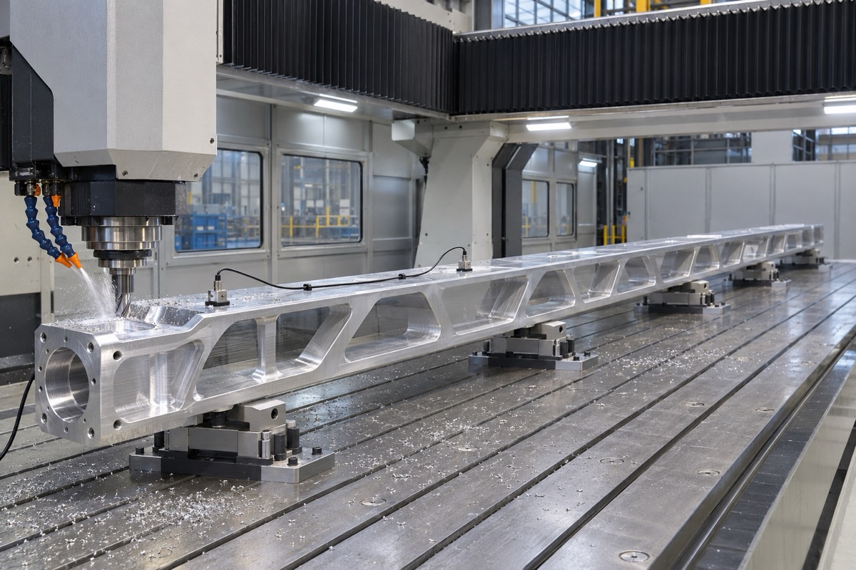
Supports, cutting tools and cutting excitations jointly determine dynamic stability.
The support position determines the clamping deformation
Tooling should support rigid nodes and avoid excessive spans while allowing the blank to be positioned without being forced flat. Multiple supports with inconsistent heights can preload bends into the part. A consistent cleaning, supporting and locking sequence must be used for each clamping. At critical stages, the clamping should be loosened or transferred to the specified support for retesting.
Residual stress management during roughing and finishing
A large proportion of aluminum alloy long beam removal may release residual stress in the plate or forging. Symmetrical, layered and alternating area removal can be used, stabilization and shape retesting can be arranged after roughing, and finishing allowances can be allocated based on actual deformation. Excessive margin in the last cut will also change the stress balance again, and the full length cannot be corrected by one re-cut.
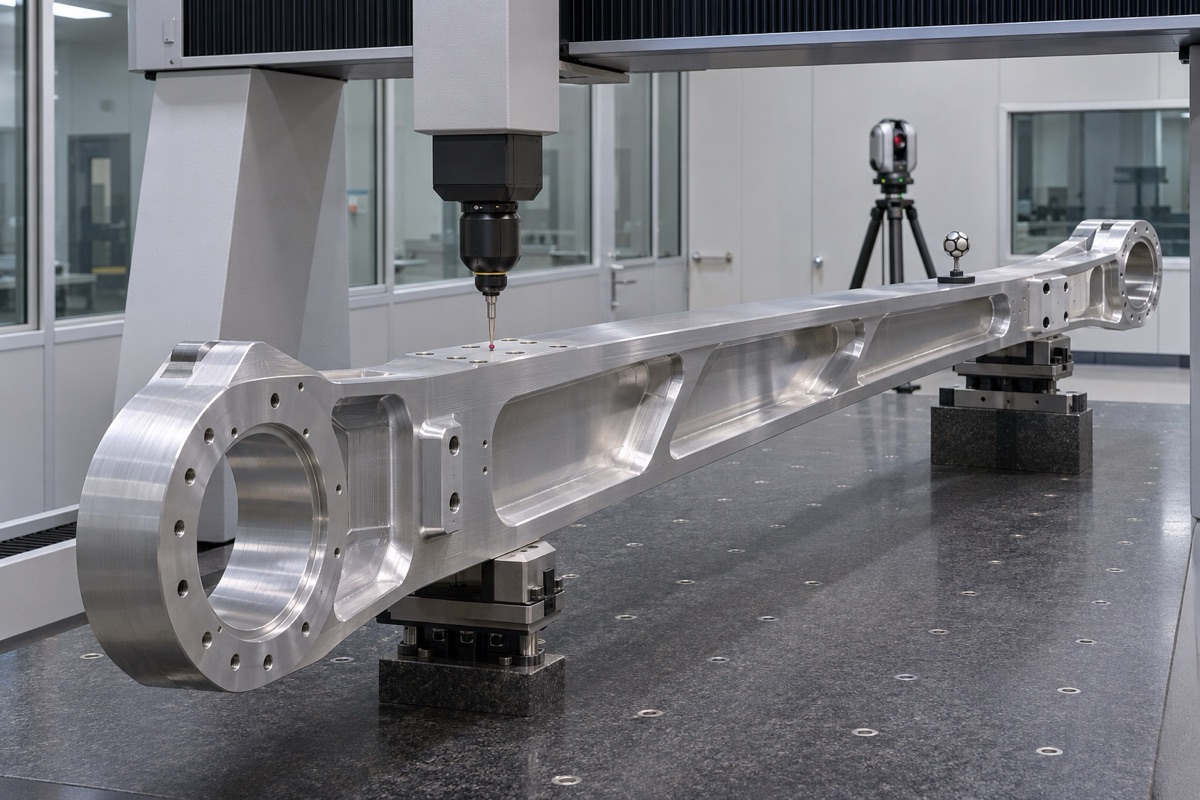
The form and position acceptance must indicate the support status, temperature and reference system.
Long knives and deep cavities require special vibration damping
Sandvik's long overhang tool information points out that long and slender tools are prone to deflection and resonance, and it is recommended to use the shortest tool assembly as possible; damping tools are a solution for specific scenarios, and it does not mean that all long-arm parts must use a certain brand of tools. The project should compare the stability, accessibility and cost of ordinary short knives, extended knives, damping knives and zoned machining.
Large size inspection must match error budget
Traditional CMMs, articulated arms, laser trackers or special measuring tools each have their own applicable scope. The measurement plan should cover both end interfaces, long datum planes, straightness and parallelism, and consider support, temperature, detection strategy and measurement uncertainty. On-machine detection at the processing site is suitable for alignment and trend confirmation, but final acceptance still requires independent methods.
Summary
Geometric accuracy requires machining around a functional datum under controlled support and temperature, and acceptance using a measuring system suitable for the size range in the free state or specified assembly state. The specific process still needs to be combined with the dynamic stiffness of the long cantilever structure, support points, clamping pre-deformation, tool extension, cutting excitation, residual stress, reference system and large-scale inspection and confirmation.
FAQ
Will increasing clamping points definitely reduce vibration?
Not necessarily. Inconsistent supports will introduce pre-deformation, clamping points should be at rigid nodes and verified for repeatability.
Can reducing the speed and feed solve all vibration marks?
No. Vibration is related to mode, number of teeth, tool extension, support and tool path, and stable combinations need to be identified.
How to avoid the influence of self-weight of long parts on CMM
Use specified supports as shown on the drawing or agreement, and establish datums and report measurement uncertainties in the same condition.
Ready to get a quote for your CNC machined parts?
Submit your engineering drawings to qiancj@oemach.com. We support prototype sampling and small-batch production with strict tolerance control.