
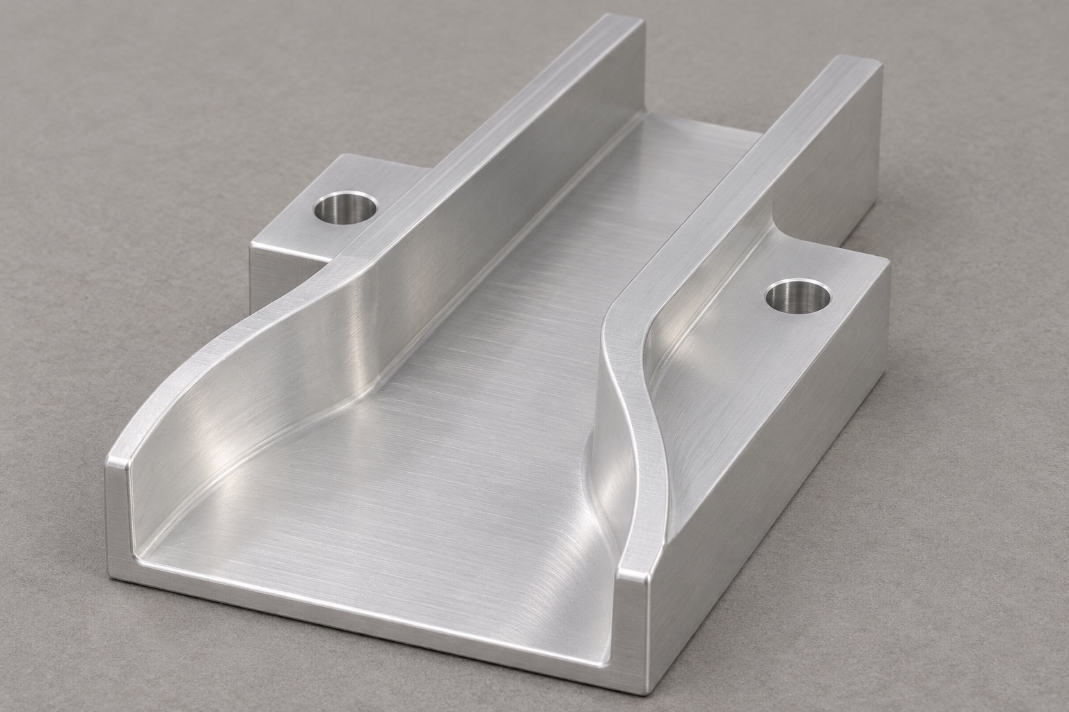
Scope the transition as a mechanical guide
Automated laboratory systems can use defined closures for sample tubes. In one representative feeder architecture, an upstream guide delivers loose caps to a short transition block that leads to a narrower lane. The block described here has a flat floor, a smooth widening at the entrance, parallel walls toward the exit and one mounting hole on each side flange. It does not orient, sense or torque the caps by itself. Define the boundaries between the upstream guide, the transition and the downstream lane. Inspect the part against that mechanical interface, rather than attributing the performance of the entire capping system to the machined block.

Use the intended closure envelope
Request the cap drawing or a controlled sample specification. The controlling outline may include a rim, external ribs, a flange or molding variation. Determine which face bears on the floor, which surfaces can touch a wall and how much tilt is permitted as the cap approaches. Include the limiting envelope rather than selecting a width from a nominal diameter. Distinguish correct approach from a condition that the machine is designed to reject elsewhere. An open chute can guide a correctly presented cap but need not reject an inverted cap unless the assembly design explicitly assigns that function to it.
Define floor continuity across both joins
The height of the channel floor relative to the mounting base is often more useful than its depth from the top of a wall. Specify the upstream and downstream floor elevations from their installed references. A cap can move freely through the block and still catch on a raised downstream lip. Compare the assembled heights, gap and edge treatment where the guides meet. If a small transition or bevel is allowed, show its dimensions and location rather than removing material during trial assembly. Keep the bench fixture revision tied to the current guide drawings so it represents the actual interfaces.
Machine the channel from stable mounting datums
Face the mounting underside and prepare the lateral and end references before roughing the channel. Support the blank under the floor and place clamps on approved external areas. As the walls become thinner, check that the clamping setup does not squeeze or twist them. Leave a defined finish allowance on the floor and walls so the transition curve can be finished without abrupt changes in tool engagement. Select a tool that reaches the inner radii and consider chip evacuation. Verify the released first piece rather than relying on the in-machine positions of the cutter and work offset alone.
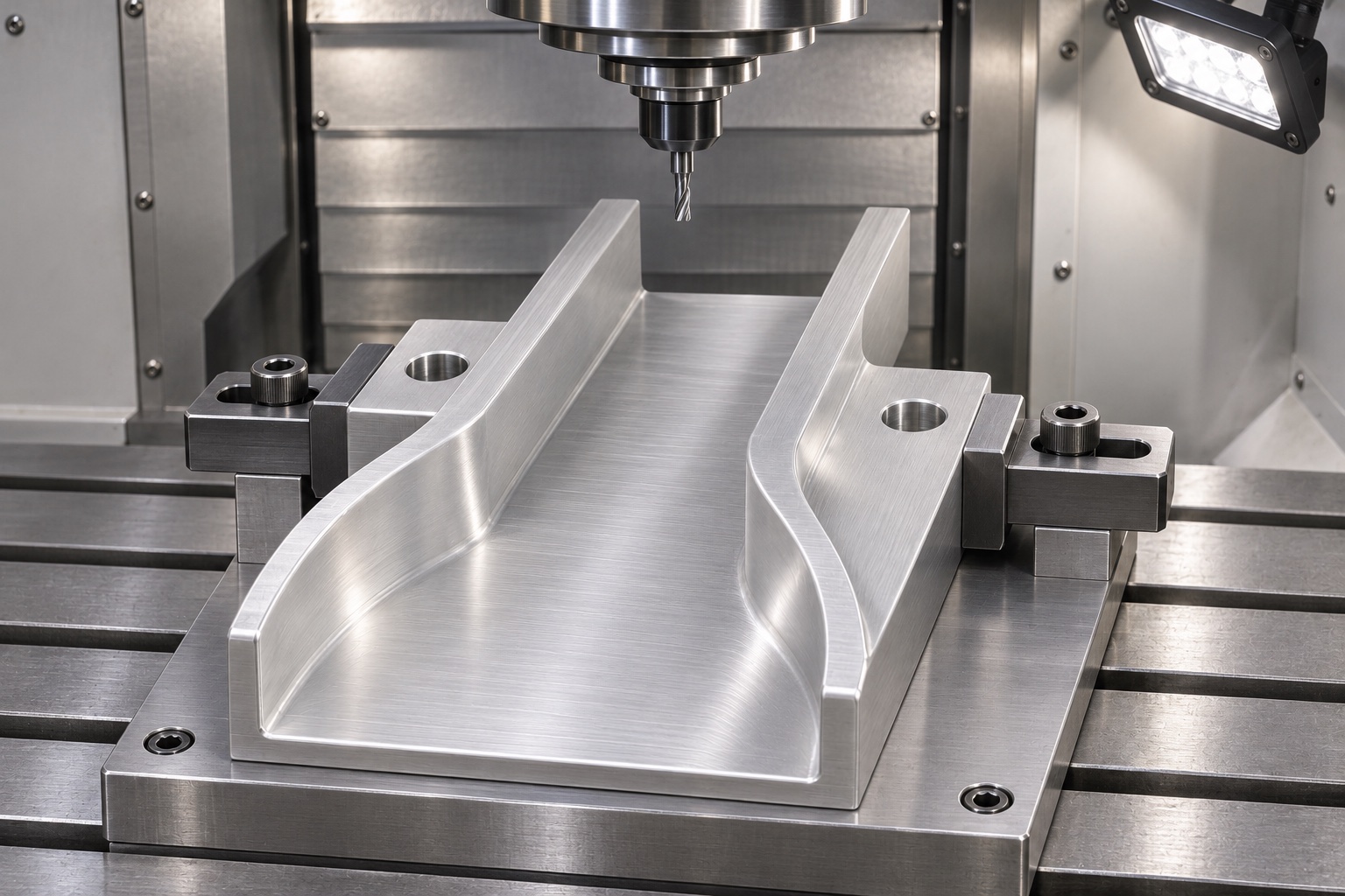
Control the widening profile, not only its endpoints
The transition can be too narrow at an intermediate location even if entrance and exit widths are within limits. Define the profile from a stable datum and identify where width is measured along its length. Use a drawing or model that resolves how the flare blends into the parallel lane. Inspect both side walls and the usable floor so a local mismatch is not hidden by an average. The width that matters can depend on cap height and any wall radius at the bottom. Specify whether the result is a point measurement, a profile comparison or an agreed fit check.
Keep mounting hardware outside the travel envelope
Use the mounting holes to attach the block, and establish location with the features the assembly actually uses. Clearance holes are not precise locating devices unless the design specifies the mating hardware and fit. Check screw head and washer envelopes where a cap approaches a flange. A burr at a hole exit can lift the base and change the floor step at the joint. If the assembly requires controlled tightening, state the applicable installed condition and verify it separately. Do not tighten or bend the block to hide a floor offset that exceeds the drawing's allowed condition.
Treat burrs and finish as separate requirements
Inspect the entrance, wall-to-floor corners, exit and mounting holes. A small protrusion can catch a cap even when the measured width is correct. Use controlled edge breaks where allowed; do not smooth an unintended step by hand without drawing approval. If the 6061 design calls for anodizing or another treatment, identify the surfaces and final dimensional condition. A polished appearance does not establish friction, particle generation or resistance to a cleaning procedure. The equipment owner defines any such tests, and the machining supplier records the agreed surface and dimensional requirements separately from those system expectations.
Select an inspection plan with real probe access
Locate the block on the mounting datum and measure the floor at several longitudinal locations. Compare the widening curve and straight lane with the specified profile or sections. Where a coordinate probe cannot reach the radius cleanly, use an appropriate alternative or record the limitation and resolve it before release. Check the mounting pattern and installed floor relationship separately. Document the support condition, instrument and measurement path so results are reproducible. Keep actual values and revision references rather than reporting that the channel merely looks smooth or that a single sample passed through it.
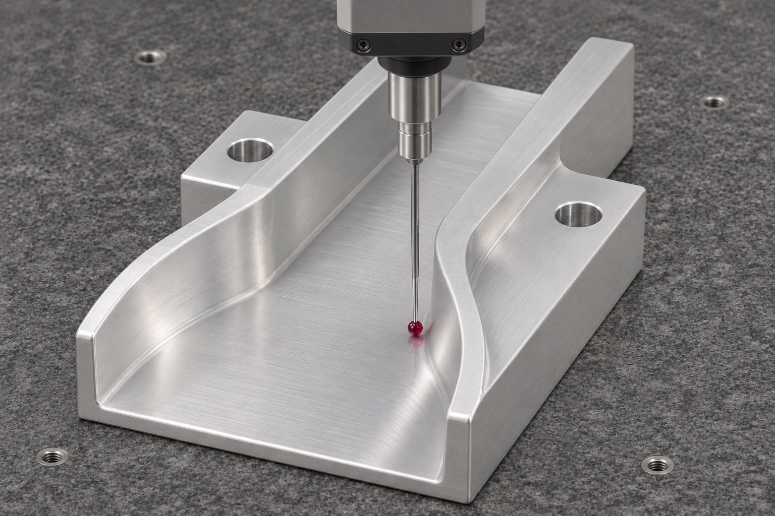
Use a nonclinical cap trial to find contact points
A clean cap surrogate or approved sample can help locate a snag. Mount the block between representative adjacent guides and use the prescribed direction and handling conditions. Observe first contact and check whether a cap catches at the entrance, inside the curve or at the exit join. If a trial includes more than one cap, describe the sample sizes and conditions. A short manual pass does not establish feed rate, cap orientation reliability, closure integrity or sample protection. Verify those properties separately on the actual equipment with its specified closures and motion settings.
Define what to do when parts fail to pass
If the cap stops at the transition curve, compare the profile and sample envelope before widening the channel. If it stalls at the exit, inspect the joint height, gap and downstream edge. If readings change when the fixture is tightened, examine seating, hole burrs and the support before changing the program. Segregate questionable parts and document the permitted correction. After any approved change, repeat the check that identified the issue. A repeat-order plan should identify changes to stock, tools, fixtures and finish that require a renewed first-piece inspection or a new assembly fit review.
Include mating and test information in an RFQ
Provide the released drawing, model, cap envelope, mating guide dimensions, hardware, quantity and finish. Mark the floor height, working walls and critical joints. State whether a supplier should build a fixture, run a limited bench trial or deliver only dimensional evidence. Identify any required material records or controlled cleanliness conditions. A quote for custom precision CNC milling should separate geometry inspection, packaging and any extra services rather than treating a generic part drawing as a complete acceptance plan. Resolve open questions about measurement and condition before production so the parties can compare results consistently.
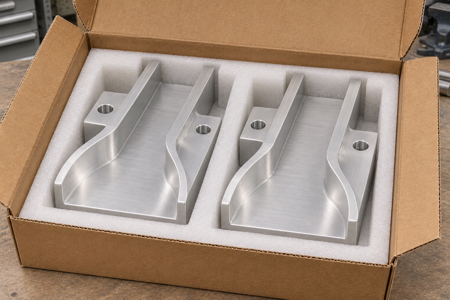
Protect the channel without trapping debris
Use separate protective compartments that support the base and prevent adjacent parts from contacting the floor or walls. Avoid tape and loose filler in the cap path. Identify each package with lot and drawing revision and link it to the inspection evidence. If the order requires a special cleanliness state, define its acceptance and handling separately; a clean-looking tray is not proof of particulate control. Ordinary protective packaging is intended to preserve the inspected surface and fit through transport. It does not establish sterility or suitability for direct contact with a specimen.
FAQ
Does this transition orient the caps?
Not by itself. In this example it guides caps already presented in the intended position. Any orientation and rejection functions belong to the defined feeder system.
Why measure floor height from the base?
The mounting base helps determine installed elevation at adjacent guides. Depth measured only from the top of a wall may not predict the actual joint step.
Is measuring entrance and exit widths enough?
No. An intermediate section can be narrower or shifted. Inspect the working profile at relevant depths and positions using the drawing-defined reference.
Can a hand trial confirm feed rate?
No. It can reveal specific mechanical interference under the trial conditions. Rate and reliability depend on the complete equipment, controls and closure population.
Why inspect after surface finishing?
If the drawing applies to the finished condition, the treatment can alter working clearances and edges. Inspect the affected features after the complete process.
What should be supplied for a quote?
Supply the drawing, model, cap envelope, adjacent guide and hardware information, quantities, finish and agreed inspection requirements, plus any specified packaging condition.

tanghangyun@oemach.com