
Separate roll support from paper drive
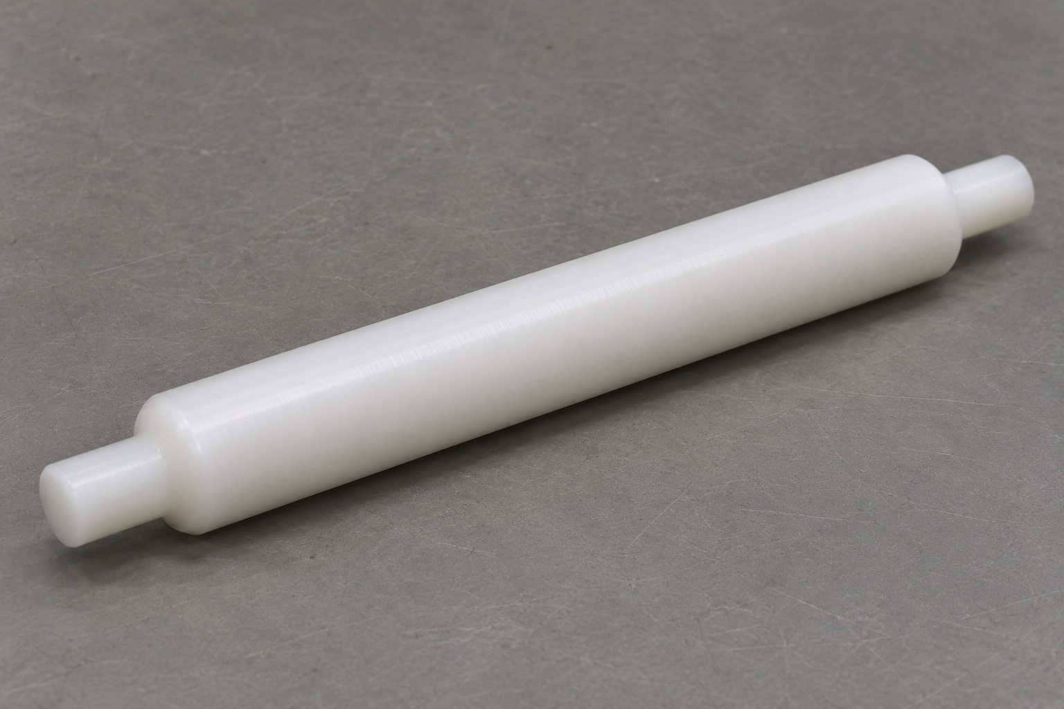
Some vital signs monitors have a thermal recorder supplied by a paper roll. In a representative recorder design, a removable spindle carries the roll core and rests in two supports. It is not the driven platen, and the surfaces do not control print pressure. The spindle has a long cylindrical body and a short, smaller journal at each end. Before specifying its dimensions, establish whether the roll turns around a stationary shaft or the shaft turns in the supports. The two designs put sliding contact at different interfaces and can require different clearances and surface criteria.

Define the roll and holder envelopes
Request limiting dimensions for the paper core, roll width, holder spacing and any retaining tabs or springs. A cardboard core may not be perfectly round, so a single inside diameter from a convenient sample is not enough to establish assembly clearance. Compare the actual installation path to the spindle drawing. A shoulder that clears when the roll is already centered can still catch during angled insertion. Identify the required clearance at the widest roll and the minimum engagement at the smallest acceptable journal. Treat a representative roll sample as a fit aid unless the design explicitly makes it an acceptance gauge.
Identify both journal references
The two journals establish how the shaft rests in the recorder. Define their diameter and usable length, and distinguish the support surface from the rounded transition into the larger roll body. Where rotational geometry matters, identify how the journal axis or common datum is established and which body section is inspected relative to it. Specifying body diameter alone does not control its eccentricity. Likewise, overall length does not control the shoulder spacing if there are separate end projections. Use a section view to distinguish end clearance, journal engagement and the axial space available for the roll core.
Limit deflection during turning
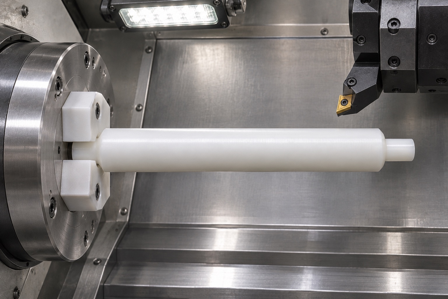
Start with suitable round stock and a workholding plan that supports a long blank without leaving marks on finished journals. A long projection can bend under cutting force; check tool sharpness, support and the depth of the final pass when taper appears. If the design cannot accept center holes, agree on a fixture and cutting sequence that do not introduce them. A second operation may be needed to finish the back journal. Locate it from the intended reference, protect the finished surface and check the resulting relationship after releasing the chuck. Do not assume that two individually correct diameters share an axis.
Specify corner geometry at the shoulders
A radius where the journal meets the body can improve handling, but its acceptable size depends on the mating support corner. If the support ends at an unrelieved corner, the radius may cause the spindle to sit high or reduce effective journal length. Show the allowed shoulder transition and the flat or cylindrical working surfaces next to it. Remove burrs and slivers without cutting into a functional journal or roll support. A shop should not interpret a generic edge-break note as permission to change the assembled span. Check the actual transition on a first piece before ordering a large repeat lot.
Use drawing-controlled polymer stock
POM-C is a material choice for this example, not a statement of suitability for every recorder. Identify the exact grade, stock form and lot documentation required. A polymer part may respond to temperature, machining heat and how long it is held in a fixture. Establish the inspection condition where those effects are relevant. A stock name or color does not establish wear life, chemical resistance or suitability for a particular cleaning procedure. If an assembly requires such evidence, the equipment owner defines the conditions and tests. Keep those questions separate from the drawing dimensions delivered by the machining supplier.
Distinguish runout from surface form
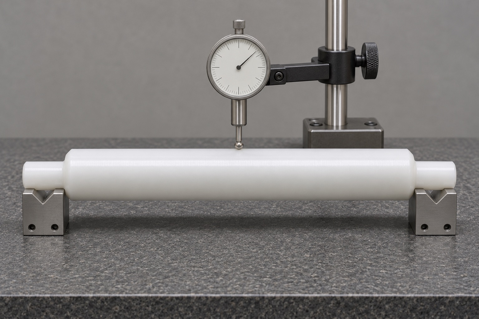
An indicator sweep over the roll body can show variation relative to the rotating support setup. It does not by itself identify whether the cause is body roundness, shaft bend, journal error or the fixture. Inspect journal sizes and relevant form separately, then compare runout at the drawing-defined sections on suitable supports. Where the journal surfaces define the reference, make sure the fixture does not substitute another center. Record the support, force and orientation so a second inspector can reproduce the check. A measurement made against chuck rotation is not automatically equivalent to a released measurement referenced to the journals.
Prevent the measuring force from masking a problem
A narrow polymer shaft can move if the indicator force is too high or the supports do not hold it consistently. Choose a measurement method and instrument with adequate uncertainty for the dimension. Check repeatability after lifting and reseating the part. If a diameter result changes with probe pressure or temperature, resolve the method before adjusting the cutting program. For an initial inspection, record actual readings at multiple longitudinal positions rather than one nominal value. Limit gauges can support defined decisions, but they do not replace variable data when the drawing asks for taper, runout or another geometric relationship.
Trial the mechanical fit without printing claims
A bench fixture can represent the recorder supports and a nonclinical roll core. Check insertion, journal engagement and axial movement using the agreed handling conditions. Note where the core first touches and whether it rotates or slides as the design intends. Do not push a binding roll through the fixture, since that hides the relevant interference and may damage the sample. A fit trial cannot establish paper tracking, print quality or the accuracy of a recorded physiological trace. Those are system-level questions for the equipment owner, using the specified paper and an approved recorder test.
Define change controls for repeat lots
Record the drawing revision, material lot, fixture and program version. On a trial lot, identify which operations can change shoulder spacing or journal alignment, then assign checks after those operations. Recheck the affected features after changing stock source, tool geometry or the second-operation fixture. If the supports are revised, confirm the mating envelope before reordering even when the spindle drawing has not changed. Keep actual process observations separate from production capability claims. A few conforming samples do not establish long-term variation, and an undocumented hand adjustment is not a repeatable production instruction.
Send an RFQ with the working relationships marked
Provide the drawing, model, roll and support envelopes, quantity, stock requirements and final inspection scope. Mark which cylindrical surfaces carry the roll and which establish the axis. Identify whether the supplier should build a fixture, use a provided mating sample or only perform dimensional inspection. State whether the order needs a finish record or particular packaging. For custom precision CNC turning, make any unresolved clearance or measurement condition explicit instead of requesting a generic tight tolerance. This allows the quote to include the right setup and inspection time without guessing at the intended use.
Protect the two journals during transit
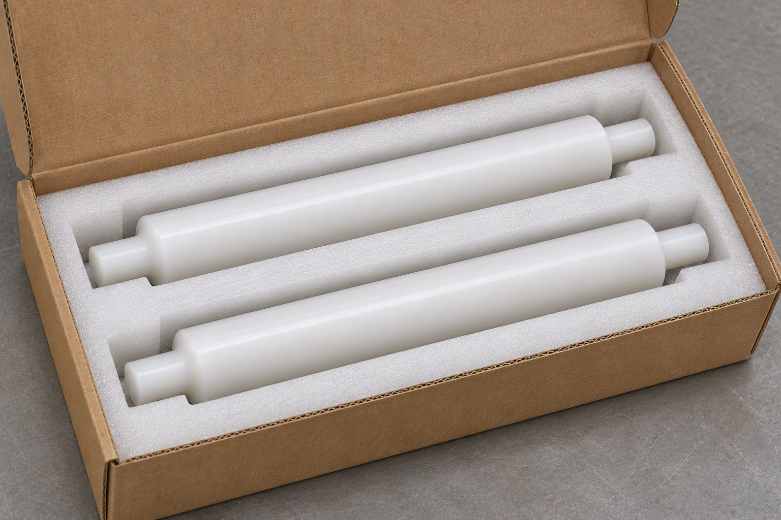
Use a straight divider or supported tray pocket that carries the shaft body and prevents contact between parts. Keep the ends clear of loose filler or adhesive, and avoid packing force that bends the spindle. Mark lot and revision on the package and link them to the inspection report. If the order specifies a controlled receipt condition, agree on the handling method and evidence separately. Ordinary protective packaging is intended to preserve geometry and surface condition; it is not a sterile barrier and does not establish cleanliness for use in a medical device.
FAQ
Is the spindle also the recorder drive roller?
Not in this example. It supports the roll, while the driven platen and other mechanisms control paper motion. Confirm the actual assembly before assigning a fit or finish.
Why check shoulder spacing as well as overall length?
Shoulder spacing can determine roll clearance even when overall length is correct. End projections and journal lengths contribute to different assembly relationships.
Can a diameter check establish runout?
No. Diameter and runout measure different characteristics. A runout result depends on the reference axis, support and the specified measurement location.
Is the spindle measured in the chuck?
In-process readings help control the cut. A final check should use the released or installed condition stated on the drawing, with the relevant journal references.
Does a free-turning roll establish print quality?
No. A fit trial only addresses the mechanical conditions it represents. Tracking and print performance require an equipment-level test with the approved configuration.
What should the first-piece report show?
It should identify the stock, drawing revision, journal diameters, shoulder spacing and any required runout or profile checks, along with the supports and inspection condition.

tanghangyun@oemach.com