
Give the key one clearly defined function
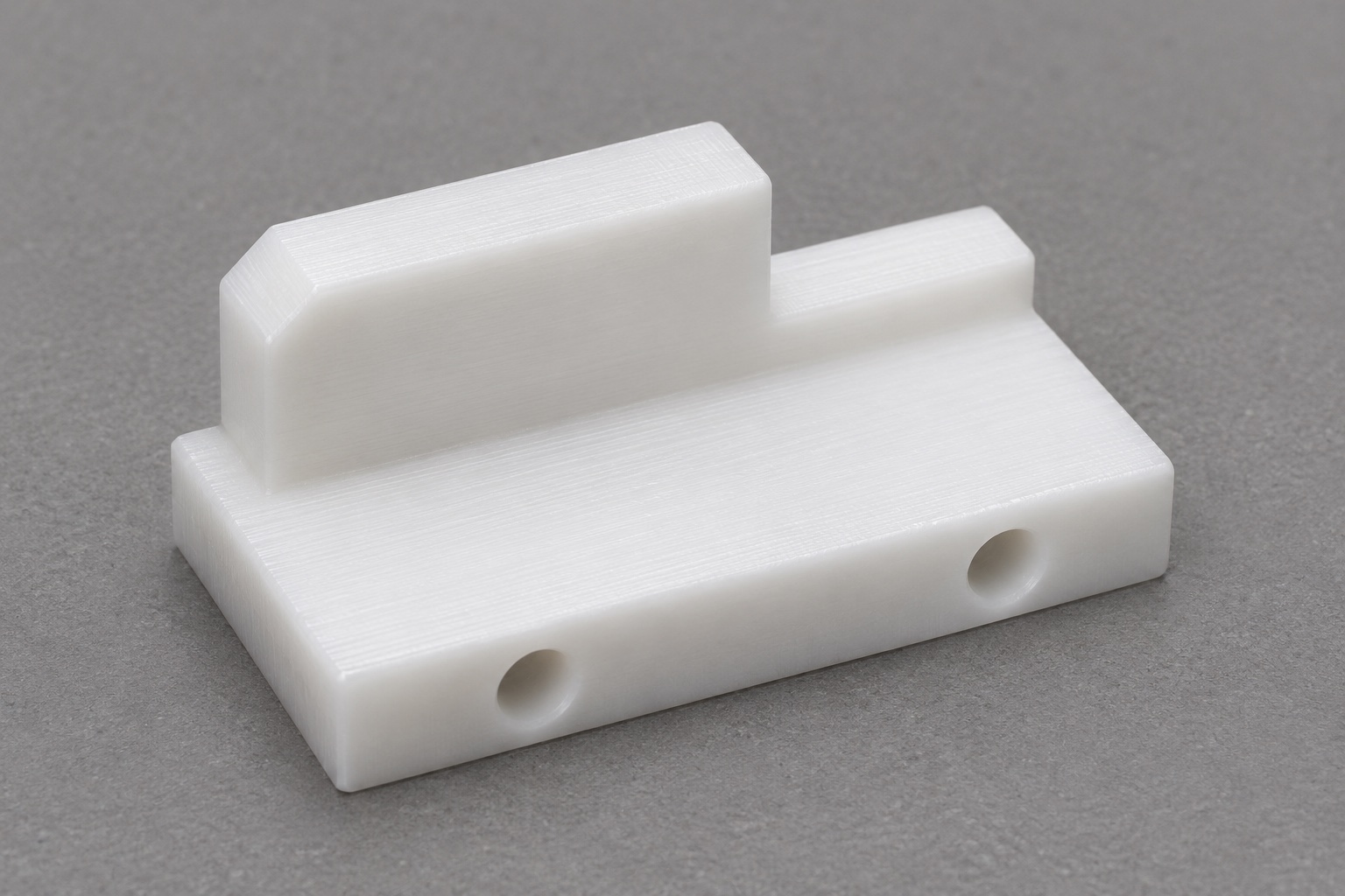
Automated laboratory equipment can carry tubes in racks. A mechanical orientation key is one possible way to distinguish the permitted entry direction of a drawing-controlled rack. The example is a natural POM-C block with a low base, two cross holes for attachment, and an asymmetric stepped tongue. One end of the tongue has a short lead-in. It is a mechanical component, not a sensor, barcode reader or interlock. Start the machining request by identifying the rack and pocket interfaces, the approach direction, and which features permit or prevent travel.

Design positive clearance and negative interference separately
In the permitted orientation, the tongue must enter the matching relief without riding on an unintended corner. In the reversed orientation, an identified shoulder should contact a defined boundary before the rack reaches the seating plane. Evaluate both conditions over the relevant tolerance stack. A key can pass a forward fit check yet fail to reject a reversed rack if too much material is removed from the asymmetric step. Draw and measure the blocking region explicitly. A supplier should not infer the reverse condition from a drawing that only shows the assembled forward position.
Locate the tongue from installed references
The seating face and side register of the key may establish location; the cross holes may merely provide screw clearance. Identify the real reference surfaces on the mating bracket. Control tongue height, side offset and step location from those references, not from an arbitrary edge that disappears in a later operation. If the design actually locates on hardware, define that interface and its fit. A good drawing can distinguish mounting-hole pitch from the relationship that determines rack entry. This makes it possible to diagnose an apparent shift without changing a nonfunctional feature.
Support the polymer during CNC milling
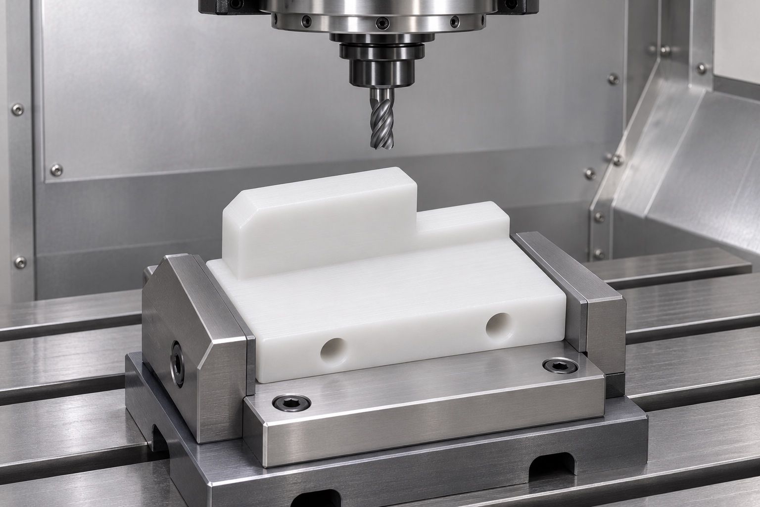
Begin with identified POM-C stock and a stable blank. Machine the base references, then rough the stepped profile while leaving material for a consistent finish pass. A thin tongue can move if it is directly squeezed against a jaw. Support the base with broad, clean contact and apply only the force needed for a stable process. Verify the profile in the released condition, especially if the part sat flat in the fixture but rocks afterward. The first-piece trial should assess burrs, surface smearing and any movement after machining, rather than treating a toolpath simulation as proof of dimensional accuracy.
Control the lead-in without weakening the block face
A short lead-in can help the permitted rack edge enter the pocket, but its length, angle and location need limits. The wrong-side face must retain its intended blocking area after deburring. Avoid an instruction to round all edges equally where one edge needs a defined profile. Inspect both the chamfer and the shoulder where it ends. A large blend may look clean while allowing the reversed part to travel farther than intended. The drawing owner can decide whether a sharp visual transition is necessary or whether a profile tolerance better describes the permitted shape.
Drill attachment holes as their own operation
Cross holes may require a fixture change or a different tool axis from the upper tongue. Transfer the locating references, verify the setup and leave room for drill exit. Inspect for burrs around both openings, especially where hardware seats or a surface contacts the bracket. In a polymer part, a raised lip can remain after a hole reads within diameter. Do not enlarge holes to make an assembly sample fit unless the drawing owner approves the change. A hole gauge and a drawing-controlled bracket trial answer different questions; record them separately.
Specify stock identity rather than color
Natural acetal appearance does not identify a particular grade, additive package or material history. Confirm POM-C stock designation, form and required records before machining. If operating temperatures, cleaning exposure or wear are relevant, obtain the actual requirements from the equipment owner rather than assuming all acetal grades are interchangeable. Specify the inspection condition if dimensions are sensitive to temperature or time after machining. A dimensional report describes the part under the stated conditions; it is not a chemical compatibility, longevity or sample integrity claim.
Measure profile and seating in the released condition
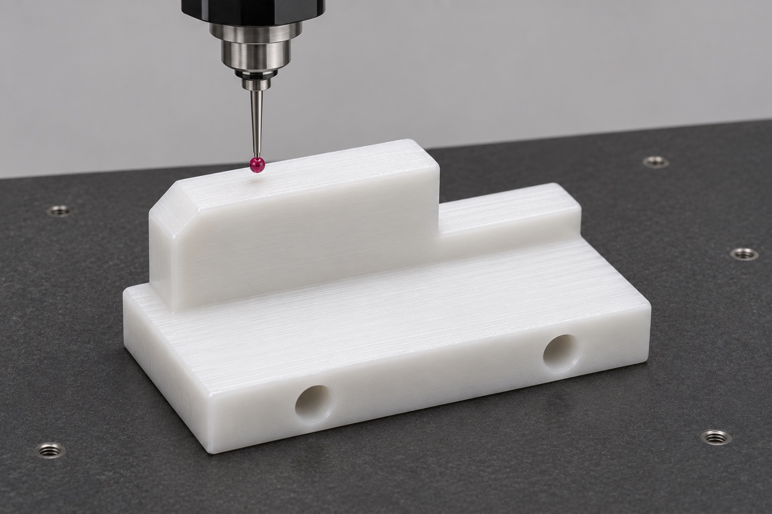
Set the part on supports that establish the drawing datum without bending the base. Check tongue height at enough points to distinguish tilt from a uniform offset. For the step, measure the position of the blocking face and confirm the adjacent lead-in profile. Inspect cross holes from their own reference scheme. Choose instruments that can resolve the allowed tolerance without appreciable probe deflection of the polymer. Record the method, support condition and key orientation in the report. A photograph may explain the setup, but it cannot replace the numerical results required by the drawing.
Use two controlled fit trials
One trial uses the permitted approach and records whether a controlled rack surrogate reaches the intended seat without forcing it. A second uses the reversed approach and observes the first point of contact and the remaining distance to the seat. Use the agreed force limit and stop condition; do not push through interference to see what breaks. Identify the surrogate and fixture revisions, and state which dimensions they represent. A bench check with one rack does not establish all tolerance combinations or prove safe operation of an automated system.
Separate acceptance evidence from instrument validation
Dimensional conformance, a manual fit observation and a complete machine test are distinct records. A compliant orientation key can still be installed in the wrong bracket revision or be affected by another feature of the rack. If the system must detect or reject a reversed rack, the equipment owner defines the system verification and any required interlocks. The machining supplier can report the component geometry and agreed bench observations. Do not claim reliable sample identification or safe instrument motion based only on the key geometry. State these boundaries in the order and the inspection plan.
Prepare a quote for the actual orientation interface
Provide the released part drawing, mating rack and bracket envelopes, both approach directions, quantity, material and packaging requirements. Mark the blocking face and permitted lead-in so the machinist can distinguish them from cosmetic edges. Define what constitutes an acceptable first-piece check and whether the supplier should make a fit fixture or use a supplied rack surrogate. Agree how drawing or stock changes will be handled for repeat lots. A clear request for custom POM-C CNC machining should state what evidence is included rather than relying on the phrase high precision.
Package the key without bending the tongue
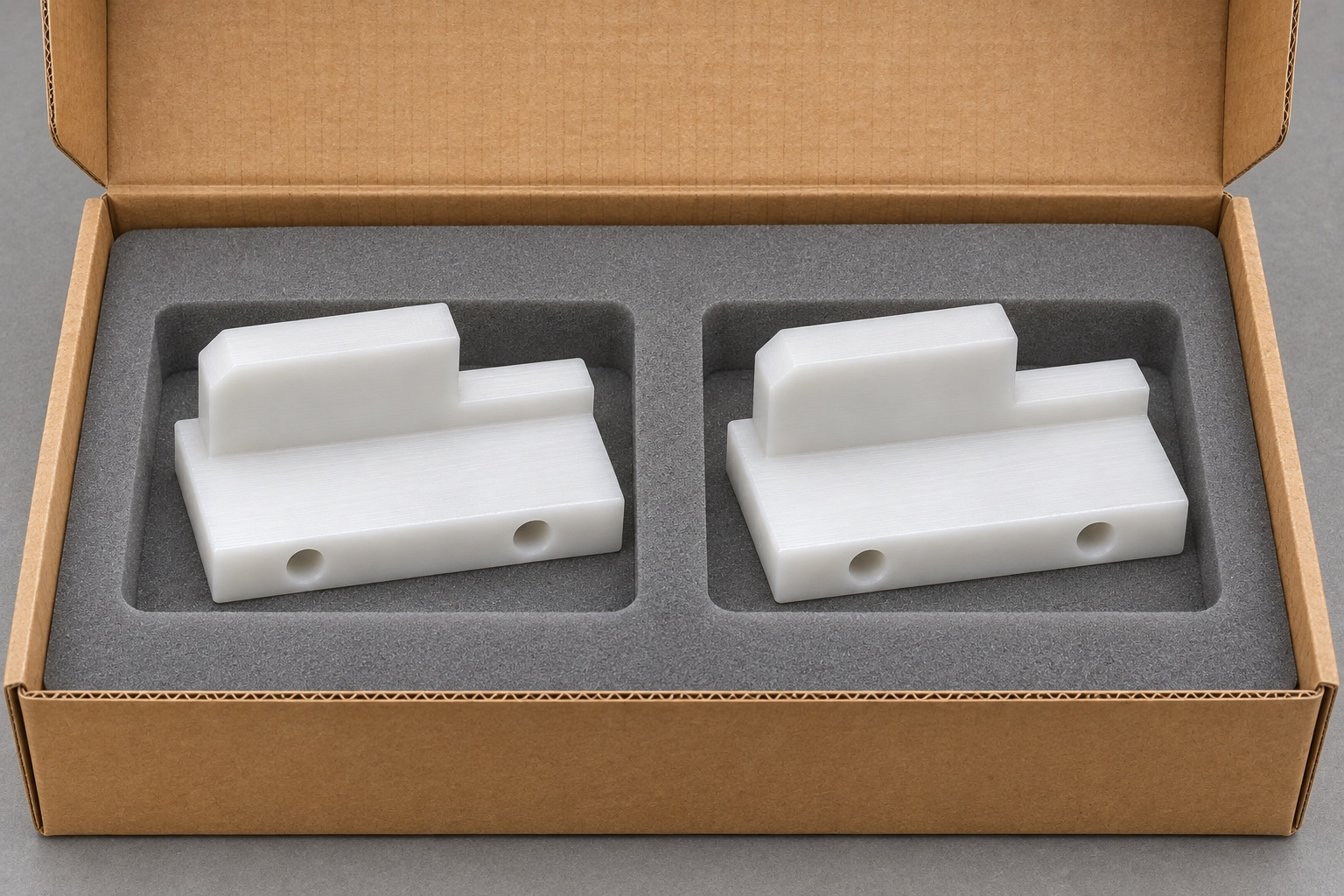
Use separate tray pockets or compatible wraps that support the base rather than pressing on the raised tongue. Prevent parts from nesting, rubbing or transferring debris around the cross holes. Keep labels on the container and identify the drawing revision and stock lot so the packing condition can be traced to the report. If a special cleanliness condition is required, specify it and its acceptance method before production. Ordinary packaging can protect geometry and surface condition during transit; it does not make the key sterile or establish its suitability for contact with specimens.
FAQ
What makes an orientation key different from a stop?
A stop limits travel at a defined position. This key uses an asymmetric profile to distinguish two approaches, so both the allowed and blocked orientations require separate acceptance criteria.
Can the lead-in be enlarged to make entry easier?
Only with an approved change. A larger chamfer can remove material needed for the blocking face or reduce the intended support area. Evaluate both orientations before approving it.
Why inspect the key outside the vise?
The vise can temporarily flatten the base or distort the tongue. Inspect in the released state unless the drawing specifies a separate controlled mounted condition.
Does a reversed rack need to be forced into the fixture?
No. Use a defined approach, force limit and stop condition. The test observes the intended interference without damaging the fixture, key or rack surrogate.
Does POM-C mean the key is suitable for specimen contact?
No. This example concerns an external mechanical orientation feature. The specified grade and dimensional acceptance do not establish compatibility, cleanliness or suitability for sample contact.
What should the first-piece report include?
Include the drawing revision, material, reference setup, tongue and step geometry, attachment holes and any separate forward and reverse trial observations. Note the fixture versions and limitations.

tanghangyun@oemach.com