
This article puts weight, static stiffness, interface shape, thermal path and overall machine performance into the same load chain to explain which areas can be removed and which areas must be retained.
Lightweighting should optimize the force transmission path rather than uniformly thinning; the bearing seat, reducer stop, fastening ring and sensor interface need sufficient local stiffness and be confirmed by assembly testing. The specific process still needs to be combined with the joint load spectrum, weight target, bearing and reducer interface, thin-wall deformation, thermal path, fastening preload, torque sensor and complete machine safety performance confirmation.
Typical problems, causes, controls and evidence
| Problem | Likely cause | Control action | Acceptance evidence |
|---|---|---|---|
| Lightweight rear bearing deformation | The local wall thickness is too thin, and the clamping and assembly preload changes the hole shape. | Keep the force transmission ring and ribs, clamp with low force and retest in the assembled state | Free/assembled hole shape, preload and stiffness data |
| The joint becomes lighter but the hysteresis increases | Housing compliance, bearing seat misalignment and fastening interface slippage | Optimize structures with load paths, control interfaces and verify torsional stiffness | Load displacement, backlash, repeatability and tightening records |
| Accuracy drifts after continuous operation | Motor reducer heat and material thermal expansion change preload and axis | Establish thermal path and thermal dimensional chain, complete steady state and cycle testing | Temperature, torque, pose drift and recovery time data |
First determine the removal area based on the load path
The joint housing bears the motor, reducer, bearings, output flange and external loads. Designs should recognize how torques, bending moments and fastening preloads flow through the structure, using stiffeners, continuous loops and closed sections to increase stiffness per unit weight. Materials away from the main force transmission path can be optimized. If they are simply thinned near the bearing seat and the stop, deformation, backlash and contact stress will be amplified.
Safety standards are not equal to parts processing standards
ISO 10218-1:2025 and ISO 10218-2:2025 cover the industrial robot body and application/unit safety respectively, and ISO/TS 15066 supplements the collaborative application requirements. The fact that the parts are processed in compliance with the drawings is only part of the evidence of system safety and cannot be used to claim that the entire machine "complies with collaborative safety." Joint stiffness, braking, control, force limiting and risk assessment are still verified by the party responsible for the entire machine.
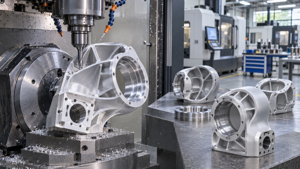
Thin-wall removal must preserve the local stiffness of the bearing seat and main force transmission paths.
Thin-wall processing requires controlling the clamping and removal sequence
Lightweight joints often have large holes, thin ribs and open mouth bodies, and their stiffness drops rapidly after rough machining. The tooling should support the rigid ring and limit the clamping force, separate rough and fine parts, remove materials symmetrically and retest after loosening the clamp. The bearing position and reducer stop should be finished in joint clamping as much as possible; if anodized, the film layer and shielding should also enter the matching dimension chain.
Bearing and tightening preload will change hole shape
A thin-walled bearing seat with acceptable roundness in its free state may become elliptical after press-fitting, bolt locking or end cover assembly. Projects should evaluate actual interference, bolt preload, and mounting supports and, if necessary, test hole pattern, rotation, and torque in representative assembly conditions. Using excessive locking force to compensate for insufficient positioning will increase friction and thermal drift.
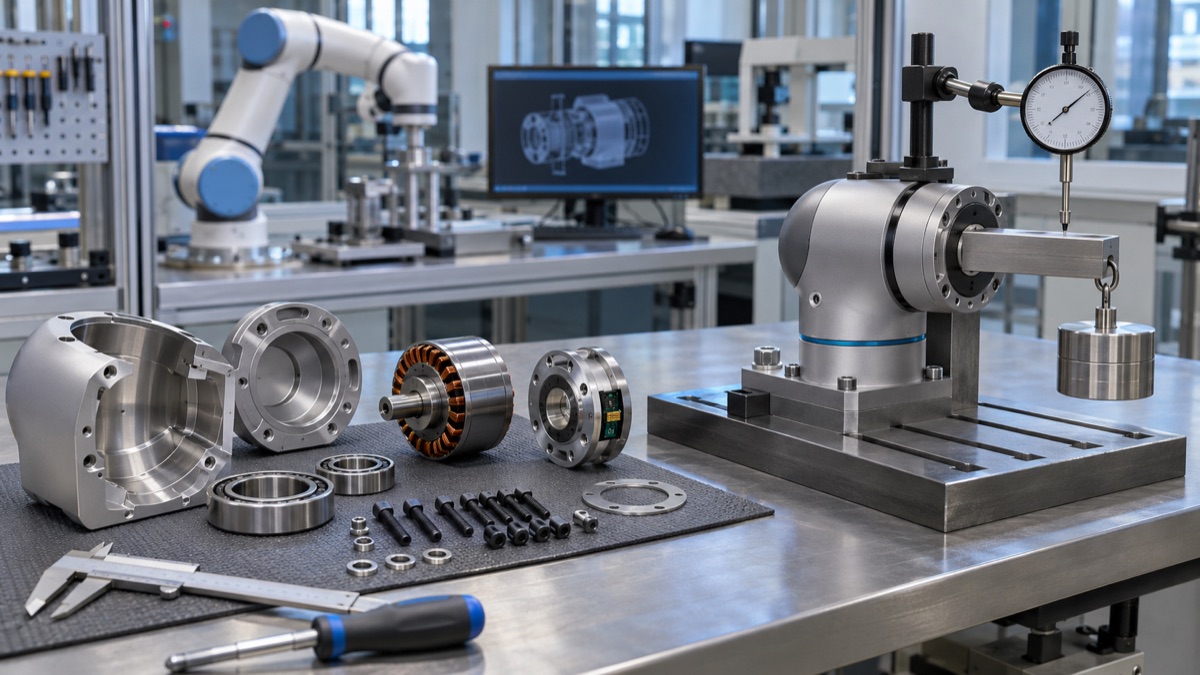
The final balance is determined by stiffness, hysteresis, temperature rise and repeatability after assembly.
Lightweight while retaining thermal stability
The heat generated by motors, drives and reduction gears is conducted through the housing, where thin walls and material distribution change the temperature gradient. Although aluminum alloy joints conduct heat quickly, thermal expansion will still change the bearing preload and axis. The prototype should record the temperature, torque, stiffness, hysteresis and posture drift, and verify the recovery after cooling. It cannot only be statically accepted at room temperature.
Overall machine performance determines whether the final balance is
ISO 9283 provides a framework of performance characteristics and test methods for industrial robots. Manufacturing clearance for cobot joints can include size, roundness, position, surface and assembly torque, but design balance also depends on joint torsional stiffness, hysteresis, repeatability, temperature rise and cycle life. After the parts data is correlated with the results of the complete machine, weight reduction can be continued in the next round with a basis.
Summary
Lightweighting should optimize the force transmission path rather than uniformly thinning; the bearing seat, reducer stop, fastening ring and sensor interface need sufficient local stiffness and be confirmed by assembly testing. The specific process still needs to be combined with the joint load spectrum, weight target, bearing and reducer interface, thin-wall deformation, thermal path, fastening preload, torque sensor and complete machine safety performance confirmation.
FAQ
Does the thicker the joint shell, the higher the rigidity?
It may increase locally, but the weight and heat will also increase. What is more effective is optimizing force transmission paths, sections and ribs.
Is the free state bearing hole qualified enough?
Not necessarily. Thin-walled structures are also evaluated for hole shape under press fit, locking, and service loads.
Can qualified parts prove the safety of collaborative robots?
No. Collaboration safety is the result of a comprehensive evaluation of robots and application systems.
Ready to get a quote for your CNC machined parts?
Submit your engineering drawings to qiancj@oemach.com. We support prototype sampling and small-batch production with strict tolerance control.