
This article illustrates that seal failure is often not a single groove width problem but is the result of a combination of grooves, seals, surfaces, case deformations, fasteners, and treatments.
The IP rating is the system performance of the finished enclosure under specified tests; neither CNC dimensional qualification nor anodizing completion alone can prove the final sealing grade. The specific process still needs to be confirmed by combining the target IP level, sealing form, O-ring compression and filling, groove size, sealing surface texture, shell deformation, surface treatment thickness, grounding point and leakage test.
Typical problems, causes, controls and evidence
| Problem | Likely cause | Control action | Acceptance evidence |
|---|---|---|---|
| The shell size is acceptable but leaking | Improper grooves, sealing surface texture, particles, or assembly compression | Design the groove according to the sealing manual and control the cleaning, lubrication and locking sequence | Groove reports, surface condition, seal batches and leak curves |
| The cover is uneven after anodizing | Thin wall residual stress, rack contact and processing thermal/chemical process superposition | Separate rough and fine parts and retest before and after processing, and optimize supports and hanging points if necessary. | Flatness, film thickness and assembly records before and after treatment |
| Abnormal grounding or shielding performance | The insulation film covers the grounding point or the contact surface is contaminated | Mask the conductive interface as shown and verify continuity after processing | Masking pattern, appearance, contact resistance and assembly traceability |
First define the IP target and real environment
IEC 60529 is used to classify the protection levels of electrical equipment enclosures. The project should specify the target level, dust or liquid method, duration, temperature and interface status and establish verification by the responsible party. The processing plant can control the shell geometry and process evidence, but cannot promise the IP rating of the entire machine based on the "sealed structure" alone. Connectors, vents, cables, and assemblies can also be leak paths.
O-ring grooves must match specific seal
The Parker O-Ring Handbook emphasizes that seal selection should combine pressure, temperature, medium, speed and size. Groove width, compression and filling rate need to be determined according to the application. Drawings should specify O-ring specifications, materials, hardness and groove geometry. Increasing compression at will may increase the assembly force, crush the seal or deform the cover, which does not mean it is more reliable.
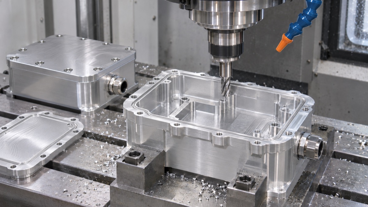
The seal groove remains empty during the machining stage to prevent the seal from being damaged by chips and tools.
Sealing surface shape and texture are equally important
Groove depth, bottom fillet, joint area and sealing surface flatness need to be controlled under the same basis. Deep knives, burrs, and scratches across the seal path can create microchannels. The finishing tool path should avoid leaving obvious joints on the sealing line, and deburring should not damage the groove edge. Particle control prior to cleaning, packaging and assembly is also a sealing process.
Thin-walled shells should consider locking deformation
Sensor housings often use thin walls and large openings to reduce weight. Cover screw preload will change the flange plane and O-ring compression. Low-force support, rough and fine separation, and free-state retesting should be used for processing; screws and stiffeners must be reasonably arranged at the design end. Leak tests should use approved torques and sequences and cannot be temporarily qualified by over-tightening.
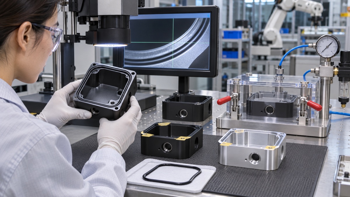
Processing should be verified with actual seal and approved assembly conditions.
Anodizing affects size and conductive interface
MIL-PRF-8625 defines anodizing requirements for many types of aluminum alloys. Treatments can change grooves, threads, and fits, and insulation films can affect grounding and shielding. The design should clarify the type, film thickness, sealing, color and masking, and retest flanges, grooves and key holes after processing. Conductive contact areas shall be masked as per controlled drawings and continuity verified.
Final assembly verification and release after processing
The dimensional report should cover the groove width and depth, flange plane, screw holes and key interfaces, and the film thickness and appearance records should be associated with the part sequence. After installing the actual seal, conduct a leakage or IP test according to the approved conditions, and record the pressure, time, temperature and assembly status. If a substitute seal is used or the surface is repaired, it should be re-evaluated and the original verification conclusion cannot be used.
Summary
The IP rating is the system performance of the finished enclosure under specified tests; neither CNC dimensional qualification nor anodizing completion alone can prove the final sealing grade. The specific process still needs to be confirmed by combining the target IP level, sealing form, O-ring compression and filling, groove size, sealing surface texture, shell deformation, surface treatment thickness, grounding point and leakage test.
FAQ
Is the shell more sealed if it is anodized?
Anodizing primarily provides surface protection and does not automatically eliminate grooves, scratches, deformations or assembly leaks.
Is the more pressure the O-ring has, the more reliable it is?
No. Excessive compression and filling may cause assembly difficulties, crush damage and housing deformation.
Can the processing plant directly commit to IP67?
Finished products need to be verified according to specified conditions; processing plants can commit to controlled size, handling and inspection evidence.
Ready to get a quote for your CNC machined parts?
Submit your engineering drawings to qiancj@oemach.com. We support prototype sampling and small-batch production with strict tolerance control.