
This article highlights the value of five-axis in reducing datum transitions and improving accessibility, but ultimate accuracy still depends on machine tool kinematics, material deformation, fixture repeat positioning, and independent inspection.
The secondary clamping error cannot be "automatically eliminated" by a coordinate offset; there must be a common closed loop of recoverable functional benchmarks, stable machine tool status, on-machine detection and independent acceptance. The specific process still needs to be combined with the integrated skeleton functional benchmark, five-axis rotation center, clamping accessibility, material removal sequence, zero point system, on-machine measurement and benchmark recovery confirmation after secondary clamping.
Typical problems, causes, controls and evidence
| Problem | Likely cause | Control action | Acceptance evidence |
|---|---|---|---|
| Five-axis one-time clamping still has axis error | Rotary axis pivot points, kinematic parameters or thermal state offsets | Perform a health check of the rotating axis before processing and verify it in a stable thermal state | Machine tool calibration, ball testing/probing and test piece processing records |
| Interface misalignment after secondary clamping | The process benchmark is inconsistent with the functional benchmark or the zero point repeatability is insufficient | Establish recoverable datums using zero point fixtures and on-machine probing corrections | Fixture repeatable positioning, probing results and independent CMM reporting |
| The skeleton is distorted after large area removal | Material residual stress and asymmetric removal change structural balance | Symmetrically layered roughing, stabilization, flip removal and finishing allowance | Free state outlines and key interface locations at each stage |
The integrated skeleton first establishes a functional baseline network
Hip, shoulder, reducer, bearing, sensor and housing interfaces may all be present on the frame. Process planning should establish the main datum, auxiliary datum and angular datum based on these functional relationships, and then arrange the blank positioning and processing sequence. If the first clamping uses a convenient blank edge and the second clamping uses a temporary hole, two sets of datum errors will be superimposed on the final axis relationship.
Five-axis linkage reduces turning but brings kinematic errors
ISO 230-7 specifies the geometric accuracy test of rotary axes, while ISO 230-12 focuses on the impact of multi-axis and synchronization errors on the test piece. The linear axes, rotary axis pivot points, angular positioning and thermal drift of a five-axis machine tool all enter the tool tip position. Before processing complex skeletons, machine tool preheating, rotary axis health inspection and necessary compensation should be completed, and the accuracy of the equipment nameplate cannot be relied upon alone.
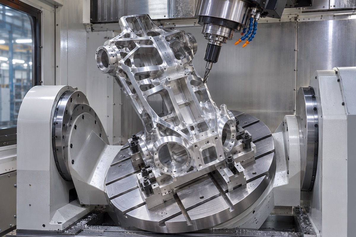
Multi-faceted interfaces should be completed around the same functional baseline and stable machine tool status as much as possible.
Material removal sequence must maintain structural balance
The integrated skeleton has a high removal rate, and the ribs and joint rings are distributed asymmetrically. Rough machining can use multiple-face alternating removal to gradually release residual stress; keep a uniform margin at key interfaces, and loosen the clamping in the intermediate stage for retesting. The tooling contact points should be located at rigid nodes to avoid clamping and pressing the blank into a state of "correct processing, loose clamping and deformation".
Secondary clamping requires recoverable physical datums
When tool accessibility or equipment stroke requires secondary clamping, the finishing datum plane, datum hole or measuring ball should be established in the first clamping, and its relationship with the functional interface should be verified. The zero-point fixture provides the basis for repeatable positioning, and on-machine detection is used to identify the actual position and attitude. When the detection result exceeds the allowable window, it should be stopped and checked for contact, burrs or deformation, rather than infinite compensation.
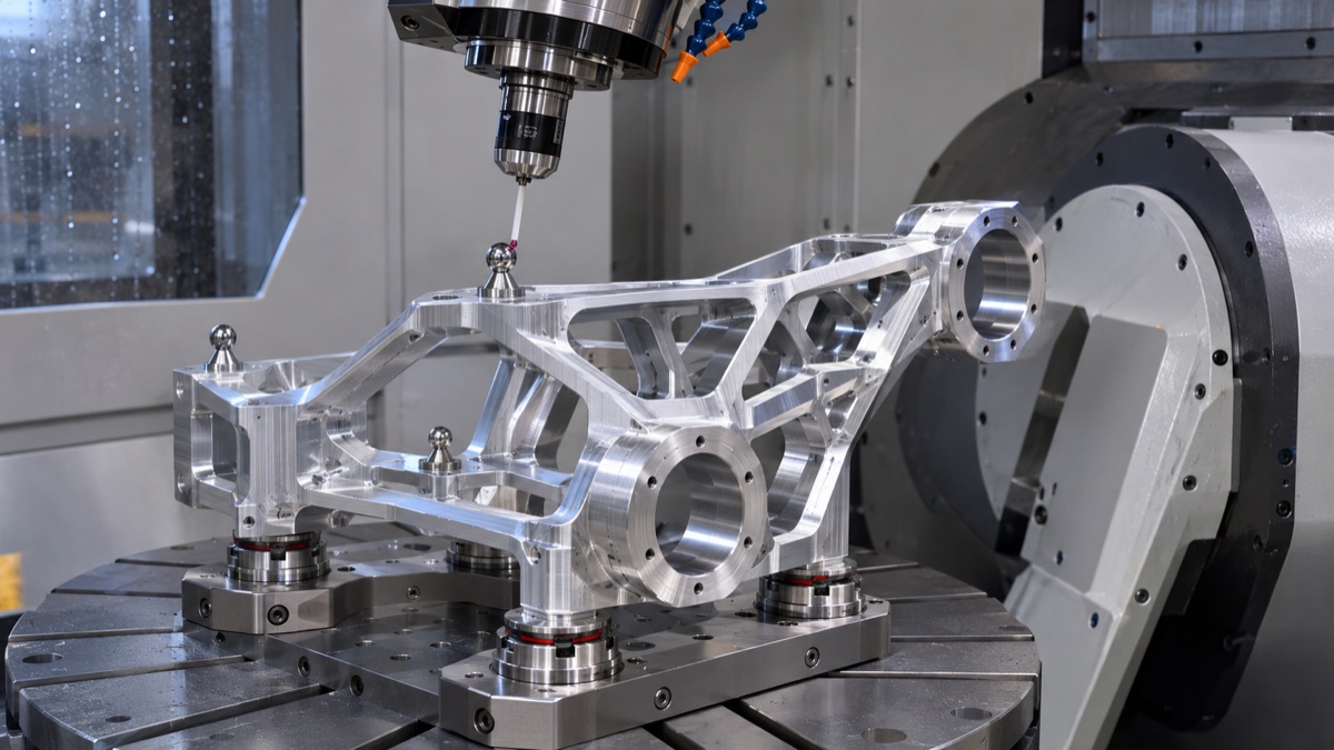
Detection is used for process alignment, and the final accuracy still needs to be independently tested and confirmed.
On-machine measurement and off-machine measurement have different responsibilities
On-machine probing is suitable for alignment, process validation and preventing apparent misalignment, but measurements still share machine tool geometry and temperature errors. The final joint hole coaxiality, end attitude and spatial position should be confirmed by an independent CMM, laser or special measuring tool. Both Heidenhain and Renishaw's materials emphasize the importance of rotary axis calibration and pivot point inspection for five-axis results.
Approval of process plan with error budget
Projects should incorporate blanks, machine tools, tooling, probing, tool deflection, temperature, and measurement uncertainty into error budgets, and allocate key characteristics to corresponding processes. The first piece needs to retain the machine tool calibration status, clamping detection, cutting program, free state and off-machine inspection data. Only when this evidence appears repeatedly can the plan be solidified into a batch process.
Summary
The secondary clamping error cannot be "automatically eliminated" by a coordinate offset; there must be a common closed loop of recoverable functional benchmarks, stable machine tool status, on-machine detection and independent acceptance. The specific process still needs to be combined with the integrated skeleton functional benchmark, five-axis rotation center, clamping accessibility, material removal sequence, zero point system, on-machine measurement and benchmark recovery confirmation after secondary clamping.
FAQ
Can five-axis machining completely eliminate secondary clamping?
Not necessarily. Part size, tool accessibility, clamping and stress relief may still require tooling changes.
Can on-machine detection pass the test to replace the three-dimensional coordinate system?
Usually not. It is suitable for process control where final acceptance still requires an independent measurement solution.
Can coordinate offset compensate for all clamping errors?
No. Contact deformation, datum damage, material springback, and machine tool kinematic errors cannot be addressed with a single offset.
Ready to get a quote for your CNC machined parts?
Submit your engineering drawings to qiancj@oemach.com. We support prototype sampling and small-batch production with strict tolerance control.