
This article distinguishes between "a certain piece is tested to be qualified" and "the process can be maintained stably", and provides the evidence chain of 5 micron size from drawing definition, processing to acceptance judgment.
±0.005 mm is not a promotional parameter for the equipment; only when dimension definition, temperature, clamping, tooling, measurement uncertainty and process distribution are controlled simultaneously can a stable implementation be discussed. The specific process still needs to be confirmed by combining the applicable dimensions and datum of ±0.005 mm, material status, micro tool runout, thin-wall clamping, temperature, burrs and measurement uncertainty.
Typical problems, causes, controls and evidence
| Problem | Likely cause | Control action | Acceptance evidence |
|---|---|---|---|
| Repeated measurements of the same size are inconsistent | Temperature, support, probe force, or measurement system uncertainty is too large | Unify constant temperature time, support and measurement procedures, and conduct research on measuring tool capabilities | Calibration status, repeatability, reproducibility and uncertainty records |
| Microhole position drift | Micro tool runout, bevel entry, chip evacuation and datum conversion effects | Short extension, stable entrance, on-machine alignment and optical/three-dimensional coordinate review | Tool runout, hole diameter, position, burr and batch data |
| The first item meets the standard but the batch cannot be maintained | Tool wear and machine tool thermal drift approach tolerance bandwidth | Set up preheat, tool life and trend control to preserve guard bands rather than limit machining | Time series dimensions, compensation, tool changes and temperature logging |
First confirm what the 5 micron tolerance controls.
±0.005 mm may be used for shaft diameter, bore diameter, groove width or location, but the machining and measurement methods for different features are completely different. Drawings should also define datums, containment requirements, surface roughness and measurement conditions. If the size is in a thin-walled or open structure, the clamped state and free state also need to be stated. Without clear specifications, even if the supplier gives the same figure, the two parties may understand it differently.
Measuring systems must be more reliable than tolerances
NIST's information on micro-scale manufacturing points out that measurement uncertainty will directly affect the acceptance or rejection of the tolerance boundary, and gives the empirical principle that the measurement capability is significantly better than the tolerance zone. For bilateral dimensions with a total width of 0.010 mm, ordinary calipers are obviously not suitable as final evidence. Pneumatic gages, comparators, optical systems, or high-capability CMMs should be selected based on characteristics and verified for repeatability, probe force, and calibration.
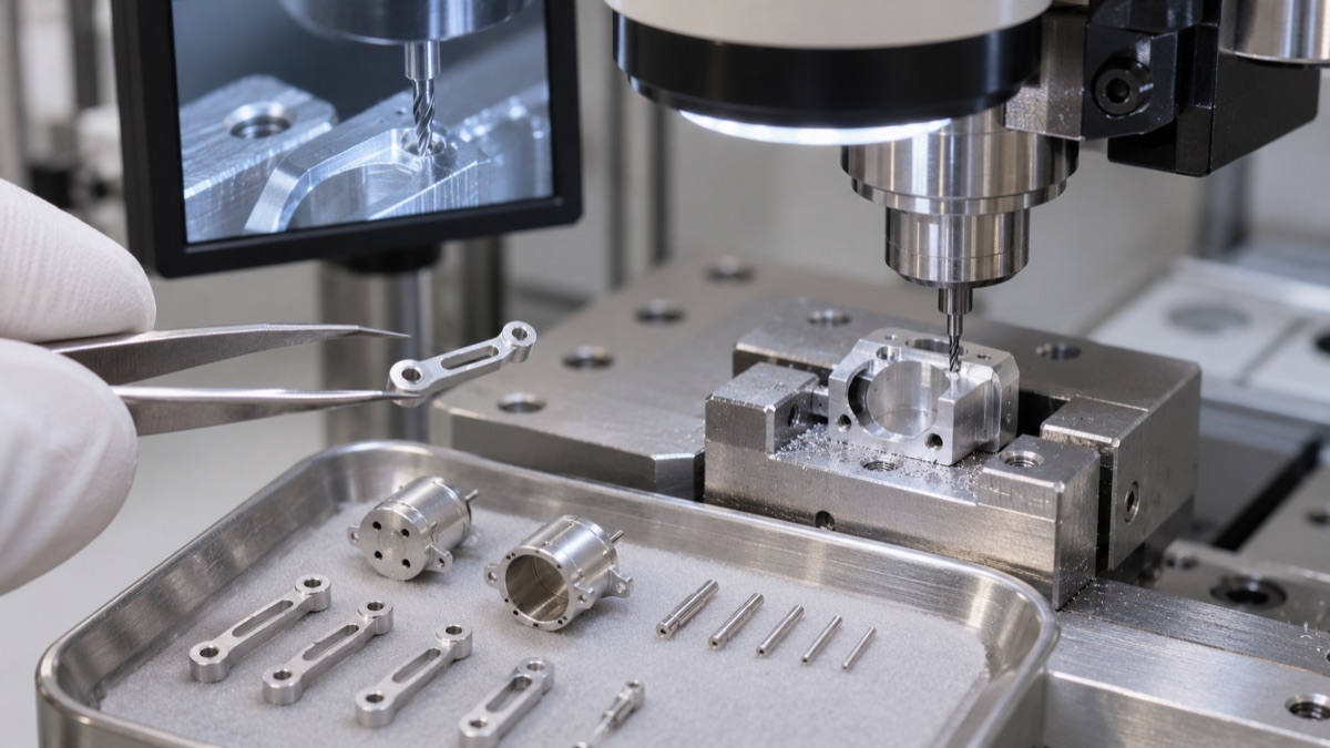
Microtool runout, chip evacuation and low-force clamping determine the basis for dimensional stability.
Temperature and support will become visible errors
Small part size does not mean thermal effects are negligible; differences in material, gage, and fixture temperatures can cause deviations in readings. The machine tool must reach a stable thermal state before processing, and the parts must have a sufficiently constant temperature before inspection. Thin and small connecting rods and motor cases will also be deformed by clamps, magnets or probes. Therefore, the measurement support must be consistent with the state of the drawing, and the environment and placement time must be recorded.
The actual runout of the micro-tool determines the cutting thickness
The smaller the tool diameter, the higher the proportion of the total runout of the spindle, tool holder, chuck and tool to the feed per tooth. Runout can overload an edge, increase burrs, and rapidly change size. Tools should have short extensions, clean clamping and actual runout measured on-machine; micro-holes also need to control entry shape, chip evacuation and tool life. Parameters should be based on stable cutting thickness, rather than simply pursuing the highest speed.
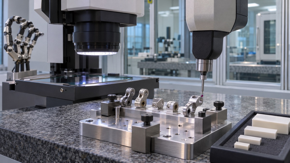
Measurement uncertainty, support and temperature must match the 5 micron tolerance.
Process design should leave protective tape for the process
If the machining average is close to the upper specification limit, even if the first part is qualified in the short term, tool wear or thermal drift will cause subsequent parts to go out of bounds. Roughing and finishing can be separated, critical dimensions are completed in a low-stress state, and compensation rules are established through intermediate measurements. Compensation can only correct predictable trends and cannot mask looseness, chipping, or random measurement fluctuations. Lots need to be monitored for distribution rather than just recording yield.
Capability commitments should be accompanied by scope and evidence
5-micron capabilities must describe materials, size ranges, feature types, batch sizes, equipment, and inspection methods. Just because a certain 10 mm shaft diameter can be maintained stably does not mean that deep holes, thin-walled grooves or large-span locations can also be achieved. When OEMach cites real cases to the outside world, it should provide the sample size, measurement system, time range and process distribution after desensitization; if there is no data, it should only describe the process plan.
Summary
±0.005 mm is not a promotional parameter for the equipment; only when dimension definition, temperature, clamping, tooling, measurement uncertainty and process distribution are controlled simultaneously can a stable implementation be discussed. The specific process still needs to be confirmed by combining the applicable dimensions and datum of ±0.005 mm, material status, micro tool runout, thin-wall clamping, temperature, burrs and measurement uncertainty.
FAQ
Is ±0.005 mm equal to the total tolerance of 0.005 mm?
No. ±0.005 mm bilaterally corresponds to a total tolerance bandwidth of 0.010 mm.
Is the resolution of three coordinates high enough to measure?
Not necessarily. Also look at uncertainty, probe, support, temperature, and specific feature accessibility.
Can the stability of the first product be proved if it passes three consecutive tests?
No. Data across time, tool life and batches are also needed to demonstrate that process distribution is controlled.
Ready to get a quote for your CNC machined parts?
Submit your engineering drawings to qiancj@oemach.com. We support prototype sampling and small-batch production with strict tolerance control.