
This article gives the correct use of 7075 cutting data: the supplier's recommended values can only be used as the starting point for specific tools and working conditions, and must be verified through trial cutting, tool runout and structural stiffness.
The stable results of 7075 structural parts come from the collaboration of material status, removal sequence, tooling support, tool system and surface treatment dimension chain. It is not just about increasing the spindle speed. The specific process still needs to be confirmed based on the specific status of 7075, blank residual stress, structural stiffness, cutting tools and machine tools, cutting fluid, critical surfaces and anodizing size compensation.
Typical problems, causes, controls and evidence
| Problem | Likely cause | Control action | Acceptance evidence |
|---|---|---|---|
| Parts warp after roughing | High removal rate releases residual stress in the plate, and the structure is asymmetrical | Remove materials symmetrically in layers, separate coarse and fine materials, and retest after the loose clamp is stable and keep a uniform margin. | Records of datum, plane and contour changes before and after rough machining |
| High speed but vibration lines appear on the surface | Insufficient tool extension, dynamic balancing, clamping or thin wall stiffness | Using tool manufacturer data as a starting point, step-by-step verification of speed and feed per tooth by vibration and chips | Tool model, runout, parameter version, surface and dimensional results |
| The fit is too poor after anodizing | Film layer and substrate consumption, masking and processing batches do not enter the size chain | Confirm the type, thickness and masking with the processor, reserve key dimensions and re-inspect after processing | Film thickness, masking map, dimensions and appearance records before and after treatment |
First lock the 7075 status and functional requirements
The 7075-T6, T651 and T73 series conditions are different in terms of strength, residual stress and stress corrosion resistance. Kaiser data shows that T6/T651 is used in high-intensity scenarios, but its corrosion resistance and processability evaluation are not "no protection required". The project should confirm the material specifications, heat batch certification and orientation based on the load, environment and blank thickness. You cannot just write "7075" in the BOM and start quoting.
Cutting parameters must be bound to specific tools and working conditions
Haas gives reference data of about 3300 sfm cutting speed and 0.010 in/tooth for 7075 hardened aluminum inserts for specific high-performance aluminum inserts. However, this value is bound to the insert, cutter body, hardness and machine tool conditions, and cannot be directly applied to small-diameter solid carbide cutters or thin-walled parts. The correct approach is to use the tool manufacturer's window as a starting point, convert the rotation speed and feed based on the actual diameter, and then check the spindle upper limit, tool dynamic balance, extension, clamping and cooling.
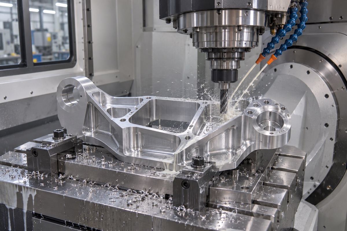
Cutting data must be verified with tool, fixture and part stiffness.
Solve deformation before high removal rate
Robot skeletons often have deep cavities, thin walls, and asymmetric ribs. Removing a large proportion of materials will release residual stress in the plates. Rough machining should adopt symmetry, layering and turning strategies, and arrange intermediate stabilization and loosening retesting if necessary. The finishing allowance should cover the shape changes after rough machining, and at the same time prevent the last cut from releasing stress again due to excessive allowance. The clamp should support the rigid area and not forcefully flatten the blank without large clamping force.
Tools and cooling determine surface integrity
Aluminum alloys require sharp edges, good chip evacuation and controlled tool runout. Built-up edge can strain the surface and change its dimensions, and secondary chips in deep cavities can also leave scratches. Sandvik data emphasizes that the use of cutting fluid for aluminum alloy finishing can reduce material smear. In fact, it must be combined with machine tool filtration, nozzle direction and workpiece cleaning. Thin-wall finishing should reduce radial load and maintain stable cutting thickness per tooth.
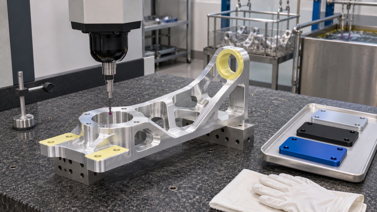
Key fits, film thickness and geometric conditions should be rechecked before and after treatment.
Anodizing must enter the process size chain
MIL-PRF-8625 distinguishes between different anodizing types and levels. The project should first determine the processing specifications, color, sealing and film thickness requirements by the designer. The film layer will grow outward and consume part of the base material. Whether the threads, bearing positions, grounding points and sealing surfaces are shielded will directly affect the fit. Processing drawings, masking drawings and processing acceptance cannot be independent of each other, and critical dimensions should be retested after processing.
Use trial cutting data to form a traceable parameter window
Public articles can provide calculation logic and manufacturer examples, but they cannot claim that there are 7075 optimal parameters that are universal across tools. The first piece should record the material batch, tool model, actual runout, RPM, feed per tooth, width and depth of cut, cooling and wear, and correlate these inputs with deformation, dimensional and surface results. Maintain consistency during volume production with approval windows and tool life management.
Summary
The stable results of 7075 structural parts come from the collaboration of material status, removal sequence, tooling support, tool system and surface treatment dimension chain. It is not just about increasing the spindle speed. The specific process still needs to be confirmed based on the specific status of 7075, blank residual stress, structural stiffness, cutting tools and machine tools, cutting fluid, critical surfaces and anodizing size compensation.
FAQ
Is 7075 necessarily more difficult to process than 6061?
It is not advisable to draw conclusions based solely on the brand name. 7075 is stronger and more sensitive to residual stress risks, but the actual difficulty is also affected by the condition, structure and tool system.
Can the cutting speed recommended by the manufacturer be used directly?
No. Recommended values are bound to tool, diameter, hardness and working conditions, and should be trial cut from the conservative end and adjusted based on machine tool, clamping and part stiffness.
Do you need to compensate for size before anodizing?
Critical fit usually needs to be evaluated, but the amount of compensation must be determined based on the specified process, film thickness, masking and handler data.
Ready to get a quote for your CNC machined parts?
Submit your engineering drawings to qiancj@oemach.com. We support prototype sampling and small-batch production with strict tolerance control.