
A small sleeve in a larger mechanical stack
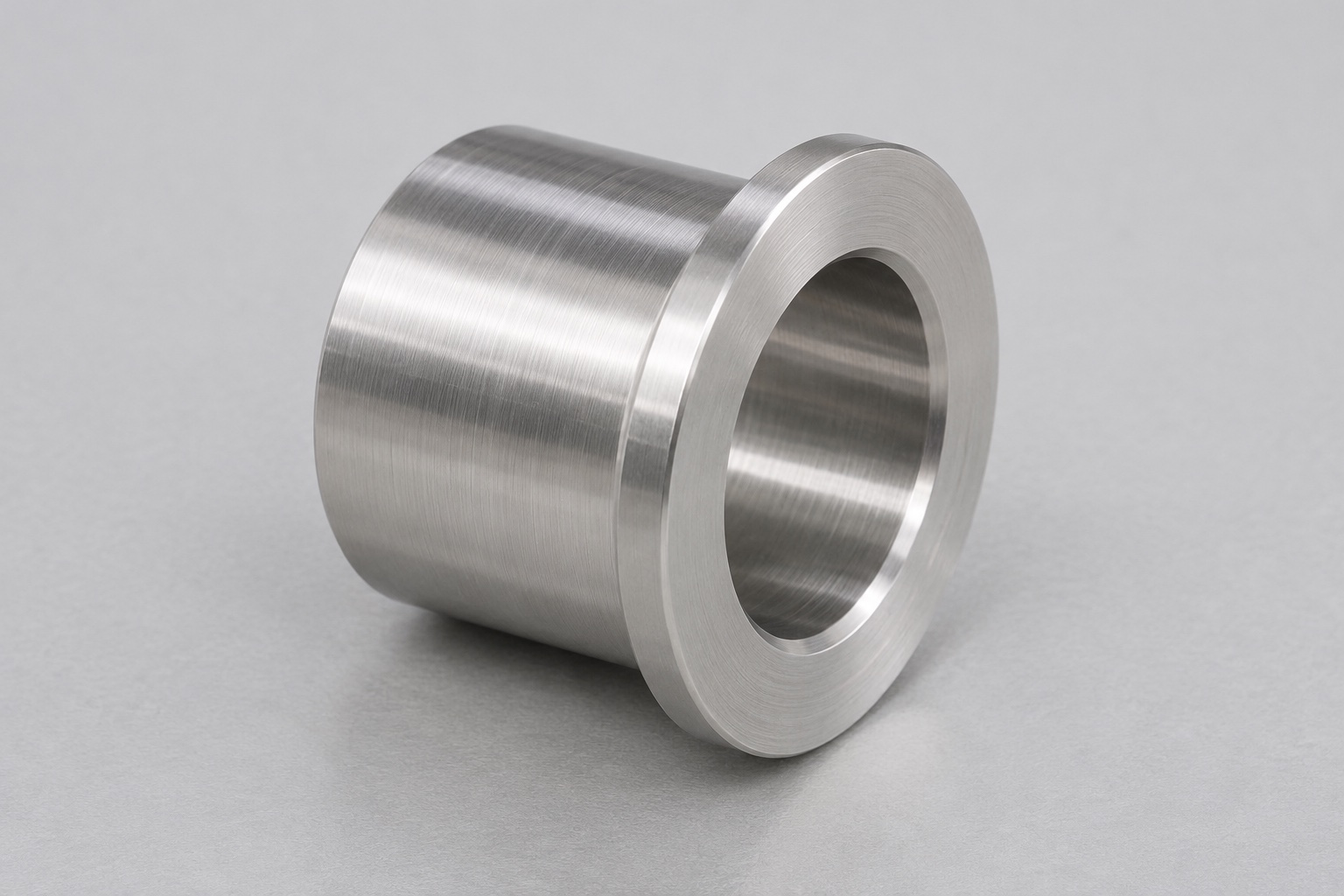
An instrument washer-disinfector can use rotary spray arms. A drawing-controlled spacer in the support stack can keep a moving arm away from an adjacent bracket or set the distance between two stationary shoulders. These are different jobs. In the example here the sleeve establishes axial spacing and has a clearance bore; it does not replace a bearing, seal, or fluid passage. The part is a short cylinder with a through bore and one external flange. Precision CNC turning is a sensible starting point because the bore, flange face and round body can share a spindle reference.

Translate axial clearance into part requirements
Start at the assembly drawing and trace the axial stack between the surfaces that stop movement. A shorter sleeve may increase clearance in one layout and reduce it in another; write the stack explicitly rather than using a general rule. Use the distance between the two working faces, not an overall length measured across an unrelated rim or radius. Ask which other parts contribute to end play, including washers, shoulders and any compliant components. The machining drawing can then identify the face-to-face dimension and the required parallelism independently of the outside diameter.
Use the bore for what it actually locates
A sleeve that clears a shaft should have a documented maximum shaft envelope, including any finish, burr allowance or local step it must pass during assembly. A sleeve that locates on the shaft calls for a different fit and may require a different verification method. Decide which case applies before choosing the diameter limits. Establish the inspection datum from the geometry that positions the part in use. Checking the bore against an unrelated cosmetic diameter can produce an impressive report with little evidence that the spacer will seat correctly.
Plan the precision CNC turning setup
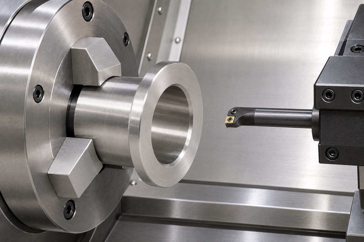
Face the flange end, drill undersize, bore to the specified envelope and turn the reference outside diameter while the workpiece remains on one spindle. That sequence can reduce reclamping error between the bore and face, provided the tool has stable reach and the stock stays supported. Check tool clearance where the flange meets the body. If the second end must be finished after parting, locate the part against a clean stop in soft jaws or a collet. Confirm the fixture does not clamp the thin rim or use a surface that the drawing expects to remain free of marks.
Separate edge break from bearing-face width
The bore entry needs enough relief to clear the intended mating corner; that does not imply a large chamfer at every edge. On a narrow flange, a generous edge break can reduce the actual contact land. Conversely, a burr left on the bore can interfere even when the measured diameter is in tolerance. Dimension the edge adjacent to the bearing face and provide a separate instruction for nonfunctional edges. If the machining drawing uses a general deburring note, highlight the locations where that note must not be interpreted as permission to blend away a working shoulder.
Specify material and finish separately
For custom 316L stainless steel machining, identify the stock specification and traceability requirements rather than treating a grade name as a complete purchase description. A finish requirement should name the target surface, its acceptance method and whether the dimension applies before or after finishing. If the equipment owner calls for passivation, define the approved process and records separately. Material identity and passivation do not establish suitability for a particular detergent, temperature or exposure duration. Those decisions belong to the equipment owner based on the actual operating environment and validation plan.
Choose a bore check that answers the question
A plug gauge can be efficient for a specified fit decision, but one successful insertion does not report taper, out-of-roundness or alignment to the working face. For a short bore, a suitable internal instrument can compare readings at multiple depths and angular positions. Record where the readings were taken, clear of the chamfer. If the geometry requires form data, use a method with the access and uncertainty to obtain it. Keep fit-gauge results separate from variable measurements so the report does not imply more than the instrument was designed to establish.
Measure face relationships on a stable support
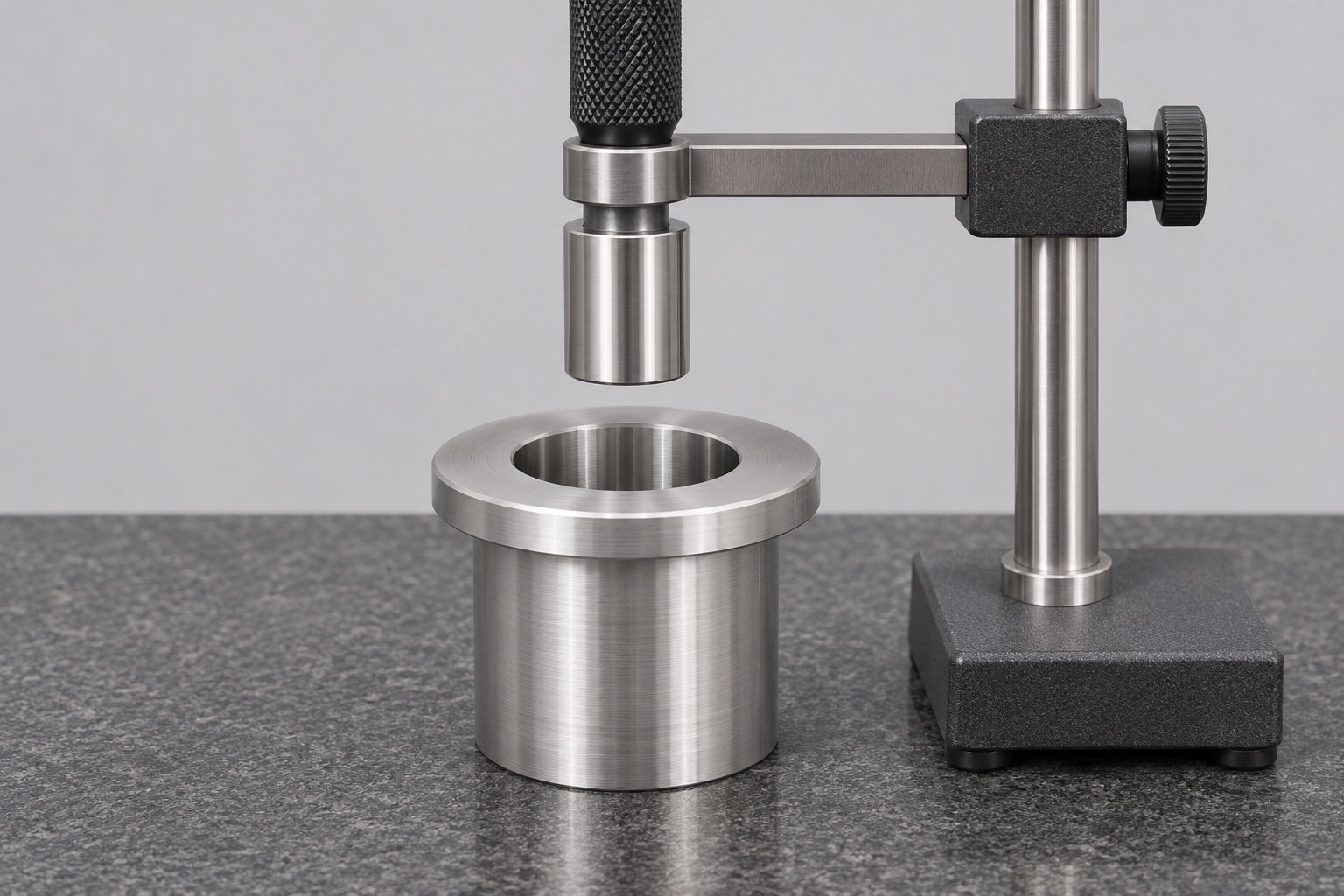
Parallelism between two spacer faces and perpendicularity to the bore axis are not interchangeable. A flat plate and an indicator may be sufficient to compare accessible faces when the support reproduces the drawing reference; the same setup may say nothing about the bore axis. If the axis matters, qualify a measuring fixture or probe strategy against it. Clean the support between readings and check for rocking before recording a result. A chip underneath the flange can tilt a short sleeve enough to dominate a face reading.
Distinguish a trial fit from equipment qualification
Use a drawing-controlled mating sample or a dedicated fixture to check how the sleeve seats, whether the edge clears the mating radius and whether the assembly stack can be put together without force. Record the fixture revision, what was observed, and any measurement limits. A smooth bench trial does not show how a complete spray system will behave over its operating envelope. It cannot establish cleaning efficacy or authorize substitution in a washer-disinfector. The equipment owner defines and executes any assembly-level or process-level evaluation.
Make lot changes visible
Tie each spacer lot to stock identification, drawing revision and the manufacturing route. For small-batch medical equipment parts, collect first-piece evidence after a stock, tool, fixture or program change where it could affect a working dimension. Review trends by feature: drifting bore size suggests a different check than variable face-to-face length or an intermittent rim mark. Document approved deviations separately. Repeated size corrections can hide damaged jaws or a misplaced stop, so investigate a pattern before treating the offset as a production fix.
Build an RFQ that can be evaluated
Supply a dimensioned drawing, model if available, material specification, required quantity and the intended post-machining finish. Identify which faces touch the stack and what a mating sample is intended to demonstrate. State whether the order needs a dimensional report, material documentation, a finish record or another agreed deliverable. For a custom spray arm spacer sleeve, that information helps distinguish a straightforward turning job from a part that requires an additional fixture or form check. Ask that any assumptions be listed in the quote before ordering a prototype.
Protect the bore and working faces in transit
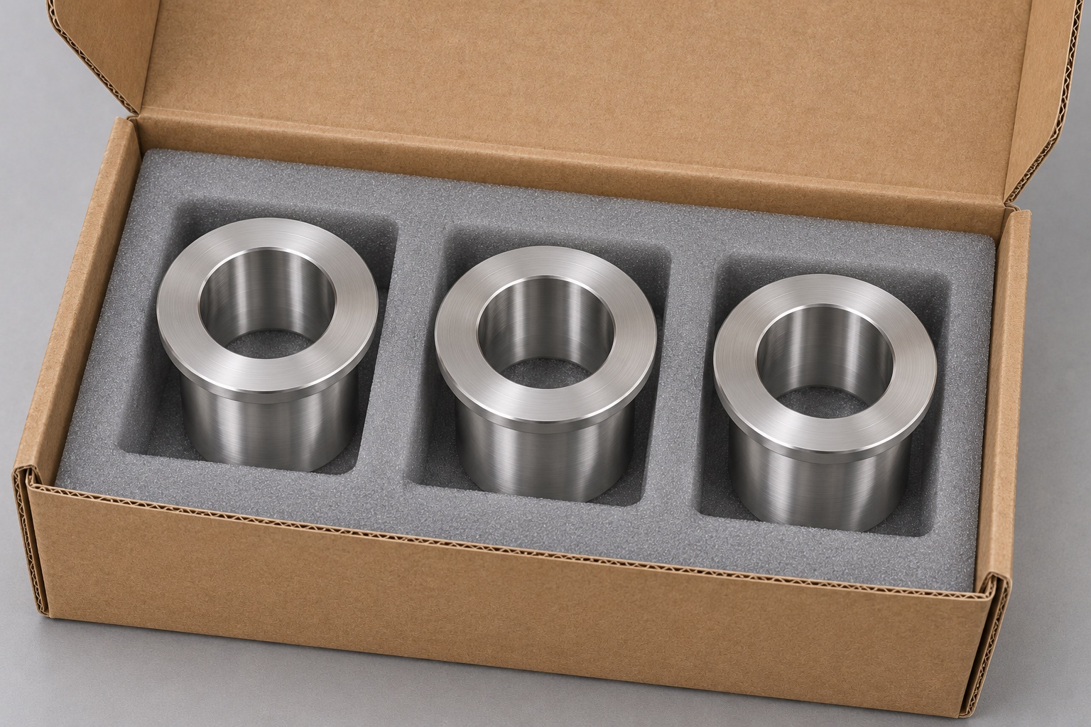
Use separate pockets or clean individual wraps to avoid sleeve-to-sleeve contact. Keep labels on the outer container so adhesive does not touch the bore or bearing land. Make the required condition at receipt explicit: ordinary protective packaging, controlled cleanliness or another agreed state. Do not infer sterile packaging from a sealed bag or a clean appearance. Pair the packaging label with the same revision and lot references used on the inspection report, and retain that link if a sample is split from the remainder of the batch.
FAQ
Can overall length replace the working face distance?
Only when the same two surfaces define both dimensions. If a rim, relief or secondary step projects farther, the drawing should identify the actual mating faces and how the distance between them is inspected.
Does a smooth bore prove the shaft will fit?
No. Surface appearance is different from size, form and alignment. Inspect the drawing-defined bore envelope and use a fit check only for the mating condition that the check is designed to reproduce.
Why inspect the part after releasing it from the chuck?
Chuck force can temporarily change a thin sleeve's shape. A free-state measurement checks the delivered geometry unless the drawing explicitly specifies a controlled restrained condition.
Can the flange and bore be turned in one operation?
Often they can if tool access and stock support permit. The second end may still need a separate operation. The acceptance checks must confirm that the second setup preserved the critical relationships.
Is passivation mandatory for every 316L spacer?
No single finish rule follows from the alloy name. Specify the finish, process requirements and evidence on the drawing or purchase specification, and have the equipment owner confirm suitability for the intended environment.
What does protective packaging establish?
It can help protect the inspected condition and preserve lot identity. It does not establish validated cleanliness, sterile condition or compatibility with a washer-disinfector cycle.

tanghangyun@oemach.com