
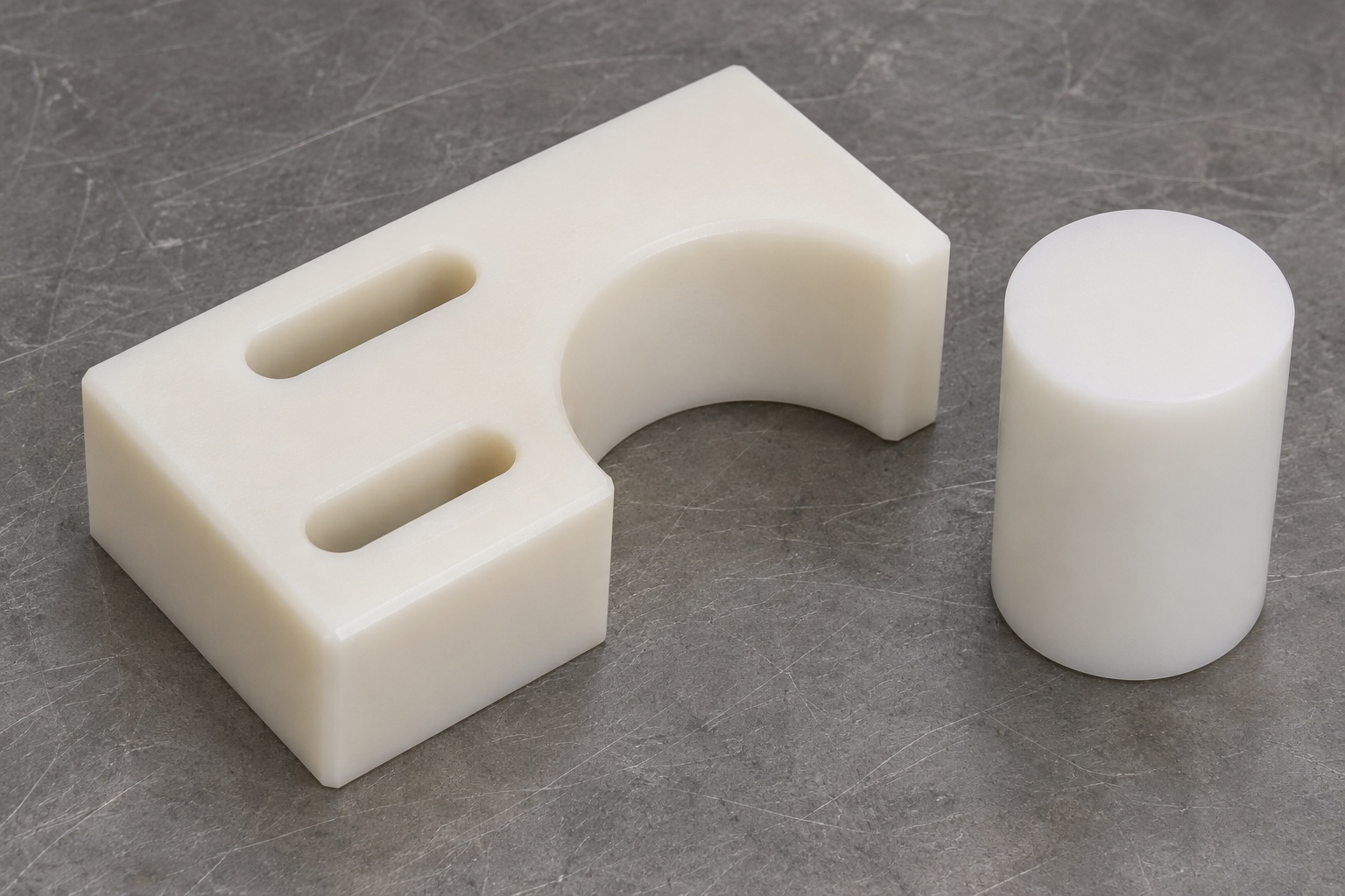
Define the guide's mechanical job
A guide shoe can establish a contact boundary for a container passing through a labeling station. This example concerns a POM-C block with one open concave wall and two parallel mounting slots. It does not specify a replacement for any labeler or a design for use with a named medication. The equipment owner defines the allowed container range, contact region, mounting position and operating conditions. A manufacturing inquiry should ask whether the approved part can be machined, measured and delivered as specified. A bench fit alone does not establish throughput, adhesion, barcode quality or correct medication identification.

Identify the envelope at the actual contact height
Obtain the approved container envelope, including its diameter range, local taper, shoulders and any labels that may already be present. A cylinder taken from a nominal diameter cannot represent every part of that shape. Identify the height at which the guide contacts the exterior and where it must remain clear. The lower and upper edges of the guide can encounter different diameters. Show a section through the installed assembly to avoid setting the same clearance for unrelated zones. If the boundary comes from an inert gauge, describe its geometry and the limits of what it represents.
Separate the arc from entry and exit transitions
An arc radius describes the nominal shape, but it does not specify where the curve starts, where it ends or how it joins a straight edge. Define the sector that controls contact and the nearby features that merely provide clearance. Consider whether edge breaks at the top and bottom affect the usable wall height. A burr can reduce local clearance even if the radius is correct on a center section. Ask for a profile check at the relevant height and review the ends independently. Do not enlarge the whole arc to compensate for a local transition that has not been measured.
Describe how the slots permit adjustment
Two elongated slots may permit movement along one direction while fasteners retain the shoe. They do not automatically define a repeatable operating position. Specify each slot's width, end geometry, orientation and position relative to the guide profile. Identify the nominal adjustment position or the separate stop that establishes location. Check that approved washer and screw-head footprints remain supported at both ends of travel. If a fixture merely centers the slots, it can miss a shift that matters at the assembled position. Include the allowed adjustment range and keep it separate from the acceptance tolerances of the part.
Select stock by grade and condition
Specify the actual POM-C grade, stock form, color and lot record required by the drawing. The appearance of an off-white block cannot prove identity or compatibility with residues and cleaning agents. Review material-removal balance before choosing stock thickness and orientation. Distortion after removing material can depend on stock condition, part geometry and restraint. Define the inspection environment or conditioning where it is important. Keep dimensional verification separate from evaluation of wear or compatibility in service. An alternative grade or color may need design approval even when it can be machined to the same nominal dimensions.
Support the web without distorting the arc
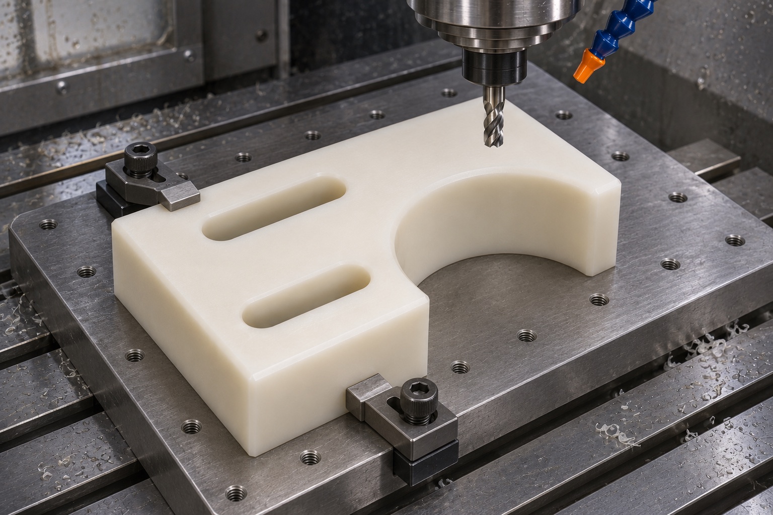
Locate the block on the intended mounting face or approved setup references. Support the web beneath the slots and keep pressure away from unsupported tips adjacent to the arc. Use enough restraint for cutting without flattening a bowed blank into an undocumented shape. If the arc or web moves after roughing, reassess allowance and the fixture before finish cutting. A probe check in the machine can guide the process, but it does not necessarily describe the released geometry. Compare the free and mounted conditions only under documented support and restraint, using the drawing to determine which result controls acceptance.
Plan the concave wall cut
A short cutter with suitable reach can finish the wall without unnecessary extension. Ensure clearance for the holder as the tool moves into the concave portion. Plan entry and exit so cutter marks do not fall in the most sensitive contact region where avoidable. Review whether the cutter geometry creates an undesired corner radius or lip at the underside. A roughing pass should leave enough material for a consistent finish pass rather than allowing the tool to alternate between cutting and rubbing. The machining plan should make the relevant arc section accessible for later measurement.
Check the slots as independent features
Measure slot width, end spacing and orientation independently of arc form. A fastener passing through one end of a slot is not proof of usable travel. Confirm that the part can move within the defined adjustment envelope on an approved reference fixture. Inspect hole and slot exits for displaced material on the mounting face. Where a washer lands near an edge, consider the entire footprint, not just its center. Keep the slot clearance separate from the location of the finished arc at a set adjustment. A documented datum scheme makes repeat inspections comparable across different fixtures.
Inspect the profile in the agreed state
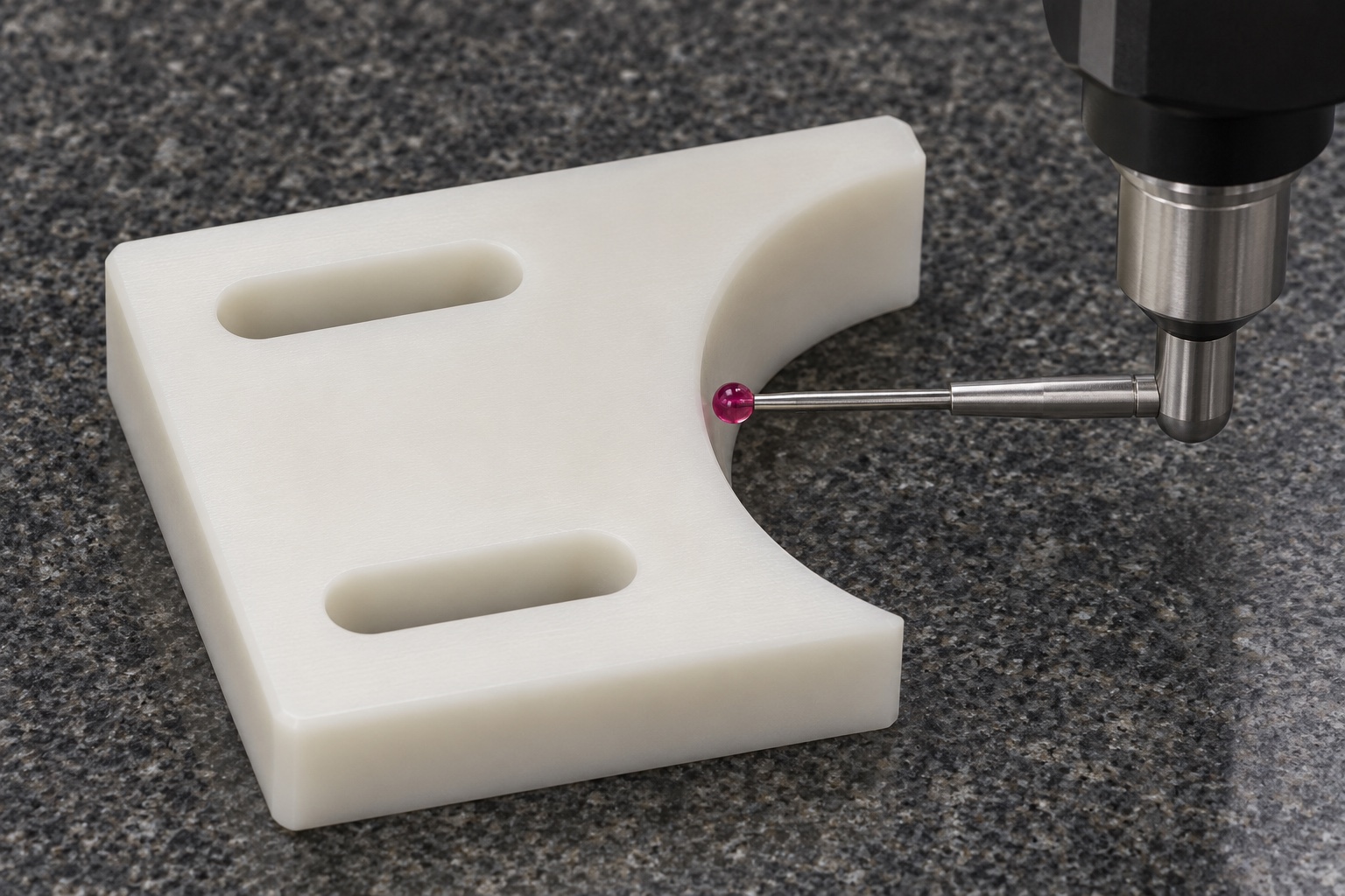
Measure the mounting face, the arc at named heights and the slot pattern in the specified condition. Select a contact or optical method that can resolve the surface without excessive measuring force or obscured edges. Record the alignment and sample locations; a best-fit circle alone may conceal local error relative to the mount. Compare an inert container reference only at the agreed setup and adjustment position. If contact is uneven, check the reference diameter, height and orientation before adjusting the part. A fit observation supplements numerical data and cannot establish the behavior of a moving, labeled container.
Set practical limits on edge cleanup
Define which arc edges can touch the container and which must remain clear. Remove raised material and loose chips using the agreed method, but preserve the contact wall and the specified entry. The exit edges of the slots deserve separate attention because a small burr can affect seating. Do not use heavy scraping to make a gauge pass; it can change the effective arc and leave uneven contact. Inspect the part under lighting that makes raised material visible. If a measurable edge break is required, record the method and the locations used rather than relying on appearance.
Protect the part without changing its shape
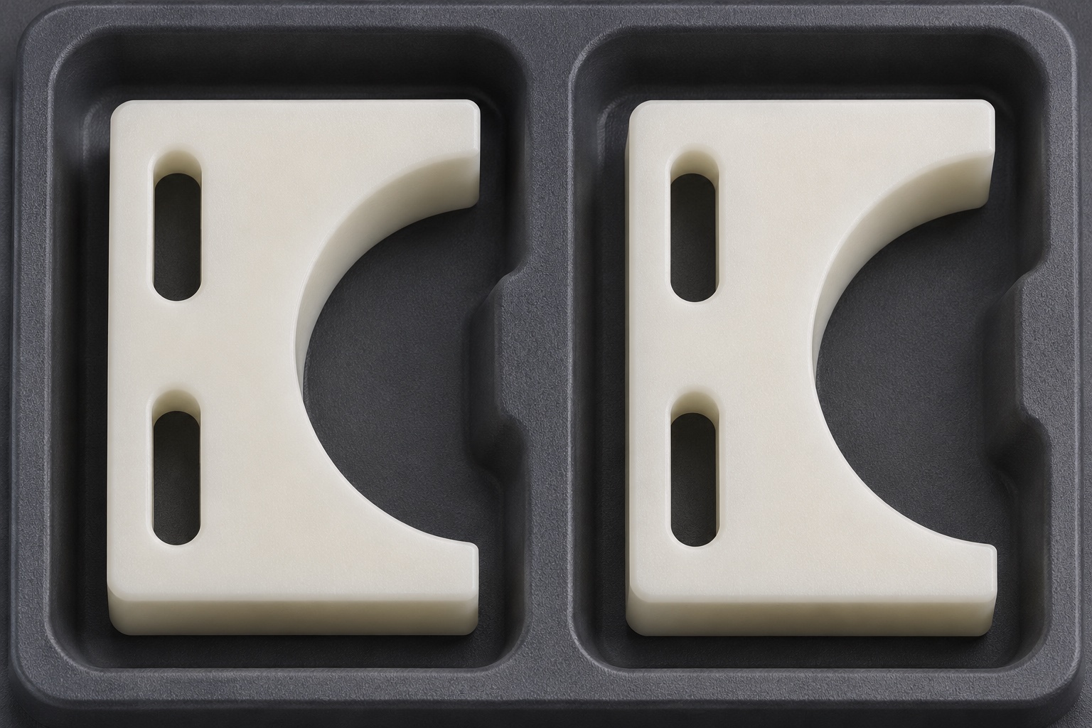
Use approved cleaning and separate packaging pockets that support the solid web without forcing the tips inward. Avoid stacking loads on the curved opening or trapping packaging fibers in the slots. Keep lot and revision identification on the package where required. Protective packaging can preserve the inspected state, but it does not establish a sterile or validated cleanliness condition. If shipping or storage may impose a particular temperature, restraint or stacking condition, agree how it will be evaluated. State the actual packing method and who owns any separate transportation qualification.
Prepare the machining inquiry around evidence
Send the controlled drawing, model and mounting section with the container envelope and contact height. Include POM-C grade, expected quantities, finish and delivery requirements. Ask for a plan covering slot and arc measurements in the agreed support condition, plus any requested inert fit check. Identify unresolved labeling or container variables instead of asking the supplier to infer them. Labeling accuracy and medication identification are system responsibilities. A useful first-article package establishes the part's geometry, material and packaging and reports what was actually observed, without claiming that the labeling station has been validated.
FAQ
Does nominal vial diameter define the guide arc?
No. The actual envelope, contact height and entry path matter. Use approved dimensions for the relevant container surfaces and keep intentional clearance separate.
Do the mounting slots establish final position?
Not by themselves. The adjustment process and any stop or locating feature define the working position. Record the specified setting for fit checks.
Why inspect more than one height on the arc?
The usable wall can vary with taper, edge breaks or tool deflection. Sampling at the specified heights helps separate local error from the nominal radius.
Can POM-C color prove the grade?
No. Verify the approved material record and stock identity. Color is not evidence of formulation, wear behavior or chemical compatibility.
Does a dry fit validate labeling accuracy?
No. It assesses geometry in a defined setup. Label placement, adhesion and barcode verification require independent equipment-level evaluation.
What should the packing avoid?
Avoid pressure on the arc tips, contact between parts and fibers in the slots. Maintain the agreed identification and cleanliness scope without claiming sterility.

tanghangyun@oemach.com